Table of Contents
Advertisement
Quick Links
Multi path reflections
FM waves, like light waves, travel in a straight direction unless reflected
off objects in their path. Because of this, two sets of waves reach your
antenna from the FM station; those that have traveled directly to the
antenna, and those that have been reflected off buildings or mountains.
When the antenna receives both kinds of signals, the two interfere with
each other and result in distorted sound and poor separation. This phe-
nomenon is called "multi path reflection". To reduce this problem, select
an antenna with good directivity and place it in the best location with
strong reception.
SPECIFICATIONS
Frequency Response:
Input Impedance:
Indicators:
Input/Output jacks:
Power:
Antenna Jack:
Antenna Impedance:
Tuning Range:
Dimensions:
Weight:
www.rolls.com
Rolls Corporation
Salt Lake City, UT
20 Hz - 12.5 kHz
100KΩ Unbalanced, 600Ω Balanced
Power LED and Clip LED
XLR balanced INPUT
RCA unbalanced input and output
Rolls PS27s 12 - 15 VDC 500mA
BNC connector
50Ω
88 - 108 MHz
6.75"w x 4.25"d x 1.6"h
1.5 lbs
1/21
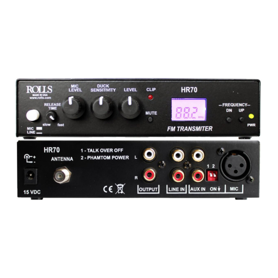
HR70
1 - TALK OVER OFF
+
2 - PHANTOM POWER
ANTENNA
-
Digital FM Transmitter
15 VDC
DUCK
MIC
LEVEL
SENSITIVITY
www.rolls.com
RELEASE
TIME
slow
fast
MIC
LINE
This device complies with Part 15 of the FCC Rules. Operation is subject
to the following two conditions: (1) this device may not cause harmful
interference, and (2) this device must accept any interference received,
including interference that may cause undesired operation.
Changes or modifications of any kind to the Rolls HR70 or its included
antenna are not approved or permitted in any way, and could void the
user's authority to operate the equipment.
Read this!
#1 - Antenna must be straight. Do not place the antenna on the ground. Do not con-
nect antenna to anything metal.
#2 - You will need to try different broadcast frequencies to get the best transmission
range. Do not transmit on a frequency that has any broadcast material as it will inter-
fere with your transmission range.
#3 - Antenna should be higher for better transmitting range. Any objects especially
metal between the transmitter and receiver will negatively affect broadcast range. Us-
ing the 6' extension cable is optimal, longer lengths will decrease range.
QUICK START OPERATION GUIDE
HR70
1 2
ON
OUTPUT
LINE IN
AUX IN
HR70
LEVEL
CLIP
FREQUENCY
103.5
MUTE
MHz
FM TRANSMITTER
MIC
DN
UP
PWR
Advertisement
Table of Contents

Related Manuals for Rolls HR70

Summary of Contents for Rolls HR70
- Page 1 20 Hz - 12.5 kHz Input Impedance: 100KΩ Unbalanced, 600Ω Balanced Changes or modifications of any kind to the Rolls HR70 or its included Indicators: Power LED and Clip LED antenna are not approved or permitted in any way, and could void the...
- Page 2 FM TRANSMITTER • MUTE: When pressed unit will MUTE. - Connect the Rolls supplied adapter to the VDC power jack of the HR70, then to an AC outlet LINE • LEVEL: Adjusts the level of output. with the proper voltage.
Need help?
Do you have a question about the HR70 and is the answer not in the manual?
Questions and answers