Table of Contents
Advertisement
Quick Links
Advertisement
Table of Contents

Related Manuals for janitza GridVis Collector

Summary of Contents for janitza GridVis Collector
- Page 1 Mobile energy data collector GridVis Collector ® User Manual (firmware 2.0.0 and higher) Janitza electronics GmbH Vor dem Polstück 6 D-35633 Lahnau Support Tel. +49 6441 9642-22 Fax +49 6441 9642-30 Email: info@janitza.de http://www.janitza.de...
- Page 2 GridVis Collector www.janitza.de ® GridVis Collector User Manual ® Portable energy data collector Doc. no: 2.099.006.1.f NOTE Date: 05/2023 Valid as of firmware: 2.0.0 Please note that certain functions of the GridVis® Collec- tor, such as WLAN, may be restricted or deactivated by...
- Page 3 Information and specifications are subject to change at any time. Please see our website at www.janitza.de for the current version.
-
Page 4: Table Of Contents
GridVis Collector www.janitza.de ® Table of contents 1. General 3. Safety 1. 1 Disclaimer 3. 1 Display of warning notices and 1. 2 Copyright notice safety information 1. 3 Technical changes 3. 2 Hazard levels 1. 4 About this user manual 3. - Page 5 GridVis Collector ® 7. 7 Main menu item "Settings" 6. Commissioning and initial configuration 7. 7. 1 LCD brightness 6. 1 Installing GridVis plug-ins in the GridVis 7. 7. 2 Time zone software from the enclosed USB flash drive 46 7.
-
Page 6: General
NOTE Please note: The screenshots of the GridVis Collector and the GridVis software shown here in the user manual may differ from the actual screens! This is due, among other things, to... -
Page 7: Defective Device/Disposal
® · Batteries and rechargeable batteries is known to be mechanically damaged, please inform · Plastics Janitza electronics GmbH. We will promptly send you a · Metals special box for dangerous goods and the corresponding warning labels for identification. or engage a certified disposal company to handle Return the device with a damaged battery, complete scrapping. -
Page 8: Product Description
With the GridVis Collector you can read out measure- ® collected by the GridVis Collector. Integration of the ® ment data from a Janitza measurement device on site, GridVis Collector into the GridVis software requires a ® ® e.g. at a transformer station. Then you can easily syn-... -
Page 9: Firmware
CBM via the USB port! The UMG 96 RM-CBM is read out via the RS-485 interface! Collector includes a USB to RS-485 converter ® (USB/RS-485 converter tested by Janitza – part no.: 15.06.107). 2. 3 Initial commissioning 2. 2. 1 Compatible devices for readout via Ethernet... - Page 10 GridVis Collector www.janitza.de ® The initial configuration (see „6. Commissioning and in- NOTE itial configuration“ on page 46) with all relevant Grid- Vis parameters, such as the GridVis project, is delivered Please note! to the GridVis Collector via the USB flash drive.
-
Page 11: Authentication
GridVis Collector ® 2. 3. 1 Authentication As of firmware 2.0.0, the communication between the GridVis Collector and the PC/server (with installed ® GridVis software) can be encrypted optionally. Authentication and encryption are done using an RSA key with a length of 1024 bits. -
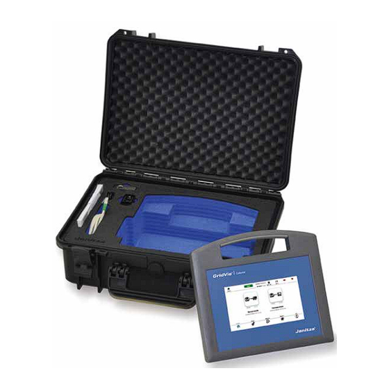
Page 12: Scope Of Delivery
GridVis Collector www.janitza.de ® 2. 4 Scope of delivery Fig.: GridVis Collector ® scope of delivery... - Page 13 GridVis Collector ® Item Part no. Designation Transport case (W x H x D: 464 mm x 176 mm x 366 mm, automatic pressure valve, water- 29.01.101 proof, dust-proof, IP67 certified) 51.00.400 Energy data collector "GridVis Collector" ® USB charger (power supply: input: 100-240 V, 50-60 Hz, 0.7 A, 34.02.001 output: 5 VDC, 2.4 A) 08.02.445...
-
Page 14: Intended Use
The EC Declaration of Conformity and the accompany- 0 to 40 °C (32-104 °F). Temperatures outside this range ing CE marking indicate that Janitza electronics GmbH can lead to impairments of the device! Please refer to has manufactured the device in accordance with the section „3. -
Page 15: Performance Characteristics
GridVis Collector ® · IEC 61000-4-4:2013 Fast transients · Readout of devices with RS-485 interfaces via USB/RS-485 converter. · IEC 61000-4-6:2009 Conducted RF disturbance, 0.15-80 MHz · Dimensions GridVis Collector (WxHxD): 270 mm x ® 247 mm x 91 mm. · Material: ASA+PC-FR (UL 94 V-0). -
Page 16: Identification Of The Device, Rating Plate
GridVis Collector www.janitza.de ® 2. 8 Identification of the device, rating plate Fig.: Rating plate... - Page 17 GridVis Collector ® Item Designation Description The device has reinforced or double insulation in the amount of the rated Symbol for "Protection class II" insulation voltage between live and touchable parts (VDE 0100 Part 410, 412.1). General warning symbol.
-
Page 18: Safety
GridVis Collector www.janitza.de ® Safety The Safety section contains information which must 3. 2 Hazard levels be observed to ensure your personal safety and avoid material damage. Warning and safety information is marked by a warning symbol, and the hazard levels are shown as follows, depending on the degree of hazard: 3. -
Page 19: Product Safety
GridVis Collector ® 3. 4 Fundamental hazards NOTE When operating electric devices, certain parts of these Indicates procedures in which there is no hazard of injury or property damage. devices can conduct hazardous voltage. Consequently, material damage and personal injury including death 3. -
Page 20: Hazards When Handling The Device And The Lithium-Ion Battery
GridVis Collector www.janitza.de ® 3. 5 Hazards when handling the device and the li- WARNING thium-ion battery Warning against contact of the device with moistu- re, water, fire, explosions, oils, acids, alkalis, gases, Lithium-ion batteries are considered to be safe when... - Page 21 GridVis Collector ® WARNING WARNING Warning against unauthorized manipulation of the Warning against misuse of the device, accessories device or the lithium-ion battery. and battery, including during charging. Opening and disassembling the device or the integrated Use of the device by unauthorized persons, especially battery can damage the device, e.g.
- Page 22 GridVis Collector www.janitza.de ® ATTENTION WARNING Warning against shock (e.g. a fall) or wilful destruc- Warning against danger of tripping and falling due to tion of the device. cables hung or routed loosely! Shocks, falls or wilful destruction of the device can lead During commissioning and operation of the device, loo- to material damage and environmental damage (e.g.
- Page 23 GridVis Collector ® ATTENTION NOTE Material damage due to incorrect maintenance of the For air travel, completely discharge the battery of the GridVis device. Please note the following: Collector. ® The use of water or other solvents, such as denatured ·...
-
Page 24: Qualified Personnel
GridVis Collector www.janitza.de ® 3. 6 Qualified personnel WARNING To avoid personal injury and material damage, only Warning against improper use of the device! qualified personnel with electrical training and expe- · If the device is not operated in accordance with the... - Page 25 GridVis Collector ®...
-
Page 26: Design Of The Device
GridVis Collector www.janitza.de ® Design of the device 4. 1 Location of connections and controls on the GridVis Collector ® Fig.: Connections and controls... - Page 27 GridVis Collector ® Item Designation Description Display 7” capacitive multi-touch colour display WLAN Integrated antenna (inaccessible from the outside) · Switches the device on and off (press the button briefly each time). · Reset of the device (press and hold button approx. 10 sec.).
-
Page 28: Housing Of The Gridvis ® Collector
GridVis Collector www.janitza.de ® 4. 2 Housing of the GridVis Collector ® WARNING The housing consists of: Warning against damage when charging the device · High-quality plastic ASA+PC+FR (UL 94 V-0) with (battery). The use of unauthorized chargers can lead to fire and high impact resistance. - Page 29 GridVis Collector ® 270 mm Fig.: Housing of the GridVis Collector ®...
-
Page 30: Transport Case For The Gridvis ® Collector
GridVis Collector www.janitza.de ® 4. 3 Transport case for the GridVis Collector ® The transport case ensures the safe transport of the GridVis Collector and protects it from moisture, ® sunlight and shocks. Furthermore, the transport case prevents the GridVis Collector from being accidentally ®... - Page 31 GridVis Collector ® Item Designation Seal Inlay in case lid. 2-coloured inlay with recess for the GridVis Collector. ® Carrying handle Pressure compensation valve Recess for USB charger (power supply unit). Latches Recess for Ethernet cable and USB/RS-485 converter.
-
Page 32: Controls And Display Elements, Operating Modes
GridVis Collector www.janitza.de ® Controls and display elements, operating modes NOTE · An internal charge controller automatically ends the 5. 1 Power supply charging process once the battery is fully charged. Recommendation: Observe the charging process The GridVis Collector has a permanently integrated ®... - Page 33 GridVis Collector ® Battery charging Battery charged Fig.: Power supply, display elements and interfaces Item Designation Status LED · Blue: Battery fully charged. · Red:Battery is charging. For additional LED statuses (operating modes), see section „4. 1 Location of connections and controls on the GridVis®...
-
Page 34: Ethernet Interface
· Connection to the network/mea- the GridVis Collector! ® surement device. · If the USB/RS-485 converter is lost, please purchase a new one from Janitza electronics GmbH and include Table: "Ethernet interface" display status the part number in the order. -
Page 35: Usb/Rs-485 Converter
GridVis Collector ® 5. 3. 1 USB/RS-485 converter ATTENTION Communication errors/malfunctions between the The scope of delivery of the GridVis Collector includes ® GridVis Collector and the measurement device! ® the USB/RS-485 converter with a length of 1.8 m (part Omitting a termination resistor when connecting a device no.: 15.06.107). -
Page 36: Switching The Gridvis ® Collector On And Off
GridVis Collector www.janitza.de ® GridVis Collector GridVis Collector 5. 4 Switching the GridVis Collector on and off ® ® ® switched on is shutting down Use the push-button switch (item 1 in Fig. "Switching the GridVis Collector on and off") to switch on the ®... - Page 37 GridVis Collector ®...
-
Page 38: Operating Modes
GridVis Collector www.janitza.de ® 5. 5 Operating modes addresses of the measurement devices are configured during initial setup via the GridVis software plug-in or directly on the GridVis Collector in the "Ethernet" ® The GridVis Collector has 2 operating modes: ®... - Page 39 GridVis Collector ® Fig.: Operating modes - Example: connection to a network and readout on site (at different transformer stations) Transformer station 1 UMG-1 GridVis software IP=192.168.5.201 database IP=10.10.10.13 Example: Connection of Transformer the GridVis Collector to ® station 2...
-
Page 40: Menu Structure
GridVis Collector www.janitza.de ® 5. 6 Menu structure Main menu Start Setup Network System Info Upload Server mode Ethernet Download Time zone WLAN Update Language Reset Device mode Factory setting Server Device list Delete records Fig.: Menu structure of the GridVis Collector ®... - Page 41 GridVis Collector ®...
-
Page 42: Start Screen
GridVis Collector www.janitza.de ® 5. 7 Start screen Fig.: Start screen... - Page 43 GridVis Collector ® Item Symbol Function Description “Functional status" display · Active function of the main menu (as of item 8). Status indicator for “Starting modules" (red): · Starts and appears automatically when the GridVis Collector is swit- ®...
- Page 44 GridVis Collector www.janitza.de ® Item Symbol Function Description Shows the status of the WLAN interface: Display · WLAN connection with the server. When the WLAN connection is "WLAN interface status" active, the symbol changes colour (blue). · No WLAN connection - symbol marked with a red X.
- Page 45 GridVis Collector ®...
-
Page 46: Commissioning And Initial Configuration
The GridVis plug-ins can be found · on the USB flash drive and 8. Automatic transfer of the configuration via the USB · on our homepage (www.janitza.de). flash drive. Installing the plug-ins in the GridVis software requi- res GridVis version 7.2.103 or higher! - Page 47 GridVis Collector ® Plug-in for 1. The configuration of the GridVis Collector in the Names of the plug-ins: ® GridVis software. 1. Collector_configuration_X.X.XX*.nbm 2. Data reception (DataReceiver) and synchronization 2. Collector_receiver_X.X.XX*.nbm of the data with the GridVis database (GridVis soft- 3.
- Page 48 GridVis Collector www.janitza.de ® Step - Install plug-ins · On the "Downloaded" tab, click the "Add plug-ins" button. · Click on the "Extras" drop-down menu in the menu · In the dialog box that appears, select your plug-in bar of the GridVis software.
- Page 49 GridVis Collector ® · The "Installation system for plug-ins" window appears. · Accept the license agreements by selecting the checkbox and clicking the "Install" button. · Proceed in the same way to install additional plug- ins. After you have installed both plug-ins, restart the Grid- Vis software.
-
Page 50: Configuring The Gridvis Collector In The Gridvis Software
GridVis Collector www.janitza.de ® 6. 2 Configuring the GridVis Collector in the ® GridVis software After the plug-in installation and restart of the GridVis software, configure the GridVis Collector in the GridVis ® software. The following example describes the configuration using the example of a new GridVis project. - Page 51 GridVis Collector ® Step 2 · In the "GridVis project" selection field, select your project path (in the example: the project “GridVis Collector"). Check the IP address of your computer in the "Win- dows Command Prompt". · Press the Windows key.
- Page 52 GridVis Collector www.janitza.de ® · The IP address, subnet mask and default gate- way of your computer appear in the window of the "Command Prompt". · The "Collector ID" can be found under the menu item "Info" in the main menu of your GridVis ®...
- Page 53 GridVis Collector ® · Configure the communication port (server port) for The GridVis Collector has two IP address ranges for IP ® the data exchange between the GridVis Collector address entry: ® and your computer (GridVis software). 1. IP address range for the devices on site (e.g. trans- former station).
-
Page 54: Assigning Measurement Devices To The Gridvis ® Collector In The Gridvis Software
After the IP address configuration of the on-site mea- surement devices, register the GridVis Collector in the ® GridVis software. Afterwards, measurement devices from your GridVis project can be assigned to the GridVis Collector in the GridVis software. · The computer with the GridVis software installed... - Page 55 ® Step 1 Step 2 In the “Collector configuration" window of your GridVis Since your GridVis software project “GridVis Collector" software, click the "Integrate Collector into the project" does not yet contain any devices, configure a measure- button. ment device (see the user manual for the measurement Make sure that the setting in the "GridVis project"...
- Page 56 GridVis Collector www.janitza.de ® Step 3 The name of the measurement device in the GridVis ® Collector (from the GridVis software) does not have to match the name of the measurement device on site. The GridVis Collector: ® The GridVis Collector links ("binding") the serial num-...
- Page 57 GridVis Collector ® In the GridVis® Collector, a tree structure appears over Recommendation several pages. This gives a better overview when there For a better overview in the GridVis software, we re- is a large number of measurement devices. This avoids...
- Page 58 GridVis Collector www.janitza.de ® Step 4 · Select the GridVis Collector item in the "Transfer- ® ring devices to a GridVis" window. Assign the measurement device of the GridVis software to the GridVis Collector. ® · Right-click on the measurement device in the Grid- Vis software.
- Page 59 GridVis Collector ® NOTE If secure communication was set in the security confi- guration in the GridVis software, this status information appears in the configuration window (see screenshot).
-
Page 60: Transferring A Gridvis Software Project To The Gridvis ® Collector
GridVis collectors. To retrieve stored data, select the project and enter the collector ID. The GridVis software creates a connection to the data- base and to previously recorded GridVis Collector data and automatically fills in the input fields (IP address, port, etc.). - Page 61 GridVis Collector ® Use an NTFS formatted USB flash drive! Otherwise the Step 2 following error message will appear: NOTE Skip this step if you do not want secure communica- tion between the GridVis Collector and the GridVis ®...
- Page 62 GridVis Collector www.janitza.de ® · The "Collector security" window appears. · Select your USB flash drive from the selection list. · Finally, click the "Export RSA key sets" button to save your RSA key pair on the USB flash drive.
- Page 63 GridVis Collector ® Step 3 Step 4 NOTE Remove your USB flash drive after the GridVis Col- ® Before you import the data from the USB flash drive to lector configuration and the security configuration the GridVis Collector, go to the start screen view (press ®...
- Page 64 GridVis Collector www.janitza.de ® · The message “Please remove the USB stick" · Then press the "Ethernet" button. appears. · The network settings appear. · Remove the USB flash drive from the GridVis Col- ® lector This is followed by an initialization that lasts about 2 minutes.
- Page 65 GridVis Collector ® · The GridVis Collector searches for connected ® measurement devices. The search process takes longer with no measurement devices. Do not cancel the process if the device list is to be loaded. · Press the "Device list" button.
- Page 66 GridVis Collector www.janitza.de ® · The measurement device added in the example A tree structure created in the GridVis software and appears. transferred to the GridVis Collector is displayed in the ® GridVis Collector display in a user-friendly manner and ®...
- Page 67 GridVis Collector ® Up to 4 measurement devices appear on the display of the GridVis Collector. Other measurement devices ® that have been assigned to a directory (e.g. transformer station) appear with an "arrow" for scrolling through the display.
-
Page 68: Integration Of Rs-485 Measurement Devices
GridVis Collector www.janitza.de ® 6. 5 Integration of RS-485 measurement devices Step 2 To be able to read measured values from RS-485 mea- Since the GridVis Collector does not search for RS- ® surement devices (UMG 103-CBM, UMG 96RM-CBM, 485 measurement devices automatically, now press the UMG 96PA), first manually configure connected measu-... - Page 69 GridVis Collector ® Pressing the "pen" icon displays 3 connection types: The window for changing the connection type appears: Select the connection type "Modbus RTU". The window for configuring the connection appears.
- Page 70 GridVis Collector www.janitza.de ® NOTE The UMG 103-CBM has automatic baud rate detection (configure 115200 baud/s in the GridVis Collector for ® this purpose). Optionally, the baud rate detection can be disabled and a fixed baud rate set for the UMG 103- CBM.
- Page 71 GridVis Collector ® If the connection test is negative, the "Connection test" When a connection is established, a green check mark appears in the device list in the "Connection" column. button is red on the display of the GridVis Collector.
-
Page 72: Secure Data Communication
GridVis Collector www.janitza.de ® 6. 6 Secure data communication Functional description Public or private networks require authentication and An RSA key pair must be generated for each GridVis ® encrypted communication. Starting with firmware Collector. The respective private RSA key is stored on version 2.0.0 the GridVis... - Page 73 GridVis Collector ® The first time you call it up, enter an administrator The RSA keys for authentication and encryption are password (Figure). This password must meet the follo- written to a USB flash drive. The GridVis Collector ®...
- Page 74 GridVis Collector www.janitza.de ® If the project is switched or the security plug-in is The encryption of small amounts of data is done direct- opened, the security plug-in requests the administrator ly via the public RSA key. password for the respective project: Records and sequences are too large for the asymme- trical RSA key.
- Page 75 GridVis Collector ® The information window of the GridVis Collector shows ® the status of the encryption.
-
Page 76: Windows Firewall
GridVis Collector www.janitza.de ® 6. 7 Windows firewall Since the GridVis Collector sends the data to the data- ® base of the GridVis software, the communication port must be enabled in both directions. This means that an active Windows firewall blocks communication. - Page 77 GridVis Collector ®...
-
Page 78: Operation
GridVis Collector www.janitza.de ® Operation 7. 1 Reading out measured values Step 2 · Connect the measurement device to the GridVis ® After the GridVis software project has been transferred Collector via the Ethernet interface (Ethernet cable to the GridVis... - Page 79 GridVis Collector ® Step 4 · When the page is opened, the GridVis Collector ® automatically searches the measurement device network for known measurement devices. Use the "Connection test" button to start this process manually. · For measurement devices that have not yet been connected to the GridVis Collector ("Binding", on...
- Page 80 GridVis Collector www.janitza.de ® Step 5 The "Manual setting" button is used for manual integra- tion of measurement devices (e.g. with IP and Modbus · Pressing the "Connection icon" button selects the address). on-site measurement device that is to be connected to the measurement device entered in the GridVis ®...
- Page 81 GridVis Collector ® Step 6 The serial number of the on-site measurement device is now linked to the measurement device entered in the · Pressing the "Read out all devices" button reads GridVis Collector. ® out all measurement devices connected to the GridVis Collector.
-
Page 82: Reading Out Measured Values From
GridVis Collector www.janitza.de ® You can then synchronize measurement devices (mea- sured values) with the database of the GridVis software or read out further measurement devices (see section „7. 3 Synchronizing measured values with the GridVis software database“ on page 84). - Page 83 GridVis Collector ® When the "Read devices" button is pressed, the Grid- Collector reads out your RS-485 measurement ® device. After the connection test, the GridVis Collector enables ® the "Read devices" button.
-
Page 84: Synchronizing Measured Values With The Gridvis Software Database
· In the "Communication port" input field, select the Collector with the database of the GridVis software. To same communication port as in the GridVis Collector do so, proceed as follows: (see section 6. 2 „Step 5“ on page 52). - Page 85 GridVis Collector ® NOTE · Data is transferred from the GridVis Collector to the ® GridVis server via the communication port. · All GridVis Collectors share one communication port. ® · Please ensure that the communication port set in the...
- Page 86 GridVis Collector www.janitza.de ® Step 2 · Connect the GridVis Collector to the network in ® which the GridVis software is running. · In the GridVis Collector, open the “Server mode" ® by pressing the button. · The data of the GridVis Collector are subsequently ®...
- Page 87 GridVis Collector ® · The “GridVis Log" window appears for checking the communication. Integrate plug-ins in the GridVis system service. Step 3 NOTE You can check the communication between the Grid- Collector and the GridVis software in the GridVis ®...
-
Page 88: Integrating Plug-Ins In The Gridvis System Service
GridVis Collector www.janitza.de ® 7. 4 Integrating plug-ins in the GridVis system service To use the GridVis Collector you need at least the ® "Professional" edition of the GridVis software (desktop). The communication channel for the data exchange (Collector Receiver) between the GridVis software and... -
Page 89: Gridvis "Service" Edition
GridVis Collector ® Collector Receiver as of the GridVis "Service" edition Step 1 Close the GridVis system service: · Press the Windows key. · The start menu with the "Search" input field appe- ars. · Enter the command “Services" and confirm with the Step 2 "Return"... - Page 90 GridVis Collector www.janitza.de ® · On your computer, open the directory "(C:)\GridVis- Data\config\Modules" and use "Ctrl + V" to paste the file from the clipboard (press "Ctrl + V"). Step 3 Make sure that the communication ports of the GridVis ®...
- Page 91 GridVis Collector ® · Save the file. Step 5 · The plug-ins are stored in the GridVis system ser- vice; start the GridVis system service. Step 4 · Open the file "server.conf" with a source code edi- tor (recommendation: "Notepad++" – available as a free download on the web!).
-
Page 92: Importing New Measurement Devices Into The Gridvis ® Collector
GridVis Collector www.janitza.de ® 7. 6 Importing new measurement devices into the GridVis Collector ® The following example shows the import of new mea- surement devices into the GridVis Collector. Measu- ® rement device names that have been changed are also transferred to the GridVis Collector in this way. - Page 93 GridVis Collector ® Step 2 · Then connect the GridVis Collector to the network ® (of the GridVis software). · In the GridVis Collector, open the “Server mode" ® by pressing the button. · The GridVis Collector synchronizes the list of mea- ®...
- Page 94 GridVis Collector www.janitza.de ® Step 3 After the restart, check the synchronization of the mea- surement device list in the GridVis Collector: ® · On the start page of the GridVis Collector user ® interface, select the "Device mode". · The list of measurement devices appears on the user interface of the GridVis Collector.
- Page 95 GridVis Collector ® · Measurement devices already connected to the GridVis Collector (see "binding" in section "Rea- ® ding out measured values" on page 89) are marked by the system with a “Trash can icon" in the last table column (e.g. UV1).
- Page 96 GridVis Collector www.janitza.de ® Step 5 NOTE · Connect the new on-site measurement device The value in the “ID" table column corresponds to the "UV2" (see example) with the GridVis Collector identification number of the measurement device in the ®...
-
Page 97: Main Menu Item "Settings
GridVis Collector ® 7. 7 Main menu item "Settings" NOTE Use the "Recycle Bin" icon to revoke the assignment of The main menu item "Settings" is used to configure incorrectly assigned measurement devices. If measured the LCD brightness, time zone and language of your... -
Page 98: Lcd Brightness
GridVis Collector www.janitza.de ® 7. 7. 1 LCD brightness 7. 7. 2 Time zone · Use the "Screen brightness" slider to configure the · Use the "Pencil" icon to select your time zone. backlight intensity of your GridVis Collector. ®... -
Page 99: Language
GridVis Collector ® 7. 7. 3 Language · Pressing the corresponding button changes the lan- guage of the GridVis Collector user interface. ® · The GridVis Collector allows a language change ® while in operation. · A language change does not require a restart of the GridVis Collector. -
Page 100: Main Menu Item "Network
GridVis Collector www.janitza.de ® 7. 8 Main menu item “Network” · Before the data transfer, switch the “Network" to WLAN in the main menu. 7. 8. 1 Ethernet · The Ethernet connection (RJ45) is disabled and data synchronization via the Ethernet connection is not possible. -
Page 101: Wlan
GridVis Collector ® In addition, the combination of data synchronization 7. 8. 2 WLAN between the GridVis Collector and the company net- ® work (computer with the GridVis software) also works NOTE via WLAN and the on-site measurement devices via Please note that certain functions of the GridVis®... - Page 102 GridVis Collector www.janitza.de ® · To search for networks in the 2.4 GHz WLAN range, press the button “Scan for networks". · The GridVis Collector displays existing WLAN ® networks and their field strength (blue field strength symbols). NOTE The WLAN antenna is integrated in the GridVis Col- ®...
-
Page 103: Server
GridVis Collector ® The GridVis Collector supports the following settings: ® Authentication: PEAP (with MSCHAPv2), TSL, TTLS. Encryption: Open, WEP, WPA2 (with CCMP and TKIP support). 7. 8. 3 Server Use the "Server" button to change server settings later on, such as ·... -
Page 104: Main Menu Item "System
GridVis Collector www.janitza.de ® 7. 9. 1 Function of "Reset" button 7. 9 Main menu item “System” The main menu item "System" gives you access to The "Reset" button in the "System" window takes you functions such as: to the area in which: ·... - Page 105 GridVis Collector ® The "Reset to factory settings?" button NOTE When the "Yes" button is pressed: · Press the "Reset to factory settings?" button · The GridVis Collector is set to the default factory ® · The "Reset" query window appears with the but- settings.
-
Page 106: Function Of "Update" Button
GridVis Collector www.janitza.de ® The “Delete records?" button NOTE When the "Yes" button is pressed: · Press the “Delete records?" button · The records in the data memory of the GridVis ® · The “Delete" query window appears with the but- Collector are deleted. - Page 107 Server mode for the firmware update. · Press the “Scan for updates" button. The GridVis ® Collector searches for firmware updates on the Janitza server via the Internet connection (port 80 - company network). · If the GridVis Collector finds a firmware update, ®...
-
Page 108: Function Of "Log" Button
The log file is used by the support department of Janit- za electronics GmbH for fault analysis. NOTE Use the "Send log file" button to send the event log (error report) to Janitza support. Please note that your GridVis Collector requires an Internet connection (with ®... -
Page 109: Clock/Battery
GridVis Collector ® Clock/Battery The internal clock of the GridVis collector is supplied The accuracy of the internal clock is +/-15 s per month ® with power by the lithium-ion battery. at a temperature of 0 °C to 40 °C (32 °F to 104 °F). -
Page 110: Technical Data
Collector/GridVis software configuration. Data exchange with the GridVis 80, 8082 Communication port for the initial installation. software Send error report to Janitza Is performed via http Support Read the measurement devices 80, 21, 502 Synchronize the internal clock with an NTP server on the 123/UDP ptbtime1.ptb.de... - Page 111 GridVis Collector ® Resolution 800 x 480 pixels, RGB LCD Touch display Capacitive, multi-touch (10 fingers) Colour 24-bit colour depth Service life of the 20000 h backlight Rechargeable battery Type Lithium ion Capacity 3350 mAh Certification UN83.3 Permanently installed, cannot be changed by the Type customer.
- Page 112 GridVis Collector www.janitza.de ® WLAN 802.11b/g/n Open, WEP, WPA 2 (with CCMP and TKIP sup- Encryption port) Authentication PEAP (with MSCHAPv2), TSL, TTLS Frequency range From 2.3995 to 2.4845 GHz Can be switched off Range 10 m Ambient temperature Operating temperature range 0° C to 40° C (32° F to 104° F)
- Page 113 GridVis Collector ® Dimensions W270 mm x H247 mm x D91 mm Material of housing ASA+PC+FR (UL 94 V-0) Interfaces USB 2.0. USB-BC 1.2 specification (USB battery charging), Mini-USB charging port charging at up to 1.5 A Ethernet connection 100Base-TX Transport case Dimensions W464 mm x H176 mm x D366 mm...
-
Page 114: Maintenance And Care
GridVis Collector www.janitza.de ® Maintenance and care 10. 1 Maintenance 10. 2 Care · This device is to be installed, operated and ATTENTION maintained exclusively by qualified personnel with electrical training and experience. Material damage due to incorrect maintenance of the ·... - Page 115 GridVis Collector ® WARNING Warning against contact of the device (batteries) with moisture, water, fire, explosions, oils, acids, alkalis, gases, vapours, dust and radiation! This can lead to a chemical reaction and to a defect of the device (material damage), or even personal injury in case of fire or explosion.
- Page 116 D-35633 Lahnau Tel.: +49 6441 - 9642-0 Fax: +49 6441 - 9642-30 Email: info@janitza.de info@janitza.de | www.janitza.de Doc. No. | 2.099.006.1.f | 05/2023 | Subject to technical changes. The current version of the document is available for download at www.janitza.de.
Need help?
Do you have a question about the GridVis Collector and is the answer not in the manual?
Questions and answers