
Related Manuals for janitza ProData 2

Summary of Contents for janitza ProData 2
- Page 1 Datalogger ProData 2 Operating instructions and technical data Janitza electronics GmbH Vor dem Polstück 1 D-35633 Lahnau Support tel. 0049 6441 9642-22 Fax 0049 6441 9642-30 E-mail: info@janitza.com Internet: http://www.janitza.com...
-
Page 2: Table Of Contents
ProData II Table of contents General Pulse counters Inspection on receipt Events Scope of delivery of ProData 2 Clock Available accessories Timer Product description Recordings Proper use Data memory ProData 2 features Rate conversion GridVis network analysis software Temperature measurement input... -
Page 3: General
EMAIL at: info@janitza.de or in part, photocopied, reprinted, or reproduced by mechanical or electronic means, or in any other manner... - Page 4 ProData II Instructions for use Please read the operating manual included in the delivery Additional legal and safety regulations required for as well as all other publications that must be referred the respective application are to be followed when using to for working with this product (in particular for the device.
- Page 5 ProData II Concerning these operating instructions These operating instructions are part of the product. • Read operating instructions before using the device. • Keep the operating instructions throughout the entire service life of the product and have them readily available for reference. •...
-
Page 6: Inspection On Receipt
ProData II Inspection on receipt The prerequisites of faultless, safe operation of this device are proper transport and proper storage, set- up and assembly, as well as careful operation and maintenance. If it can be assumed that risk-free operation is no longer possible, the unit must be immediately put out of operation and secured against being put back into operation again. -
Page 7: Available Accessories
ProData II Scope of delivery of ProData 2 Number Part no. Description 52.24.001 ProData 2 33.03.168 Operating instructions 51.00.116 CD with following content - GridVis programming software - GridVis functional description 10.01.855 Screw-type terminal, pluggable, 2-pin (supply voltage) 10.01.873 Screw-type terminal, pluggable, 6-pin (digital/pulse inputs) 10.01.861... -
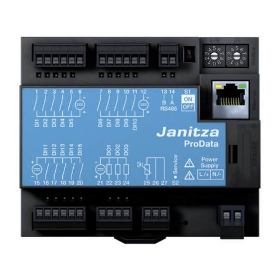
Page 8: Product Description
ProData II Product description Proper use The ProData 2 is designed for fixed installation (mounting rail assembly) in low voltage switchgear and is suitable for recording and saving counter values and process data. The data can be used to evaluate the energy consumption and operating hours, or to monitor switching states and faults in buildings, production facilities, etc. -
Page 9: Prodata 2 Features
• Configurable records, can be read out via RS485 and Ethernet Use as a Modbus RTU slave is not possible in this mode. The ProData 2 can only forward queries to a Modbus slave device; it cannot query Modbus slave devices independently. -
Page 10: Gridvis Network Analysis Software
GridVis programming software. the scope of delivery. For this, a PC must be connected to the ProData 2 via a serial interface (RS485) or via The Modbus protocol can be used to change and Ethernet (see the connection variants). - Page 11 ProData II...
-
Page 12: Connection Variants
ProData 2 ProData 2 (twisted patch cable) UMG 96RM (twisted patch cable) Connection of a ProData 2 via a UMG 604 as a gateway. Connection of a ProData 2 to a PC via Ethernet. ProData 2 UMG 604 ProData 2... - Page 13 ProData II Connection of a ProData 2 with gateway function to Connecting a ProData 2 as a Modbus slave device. a PC via Ethernet. ProData 2 UMG 103 (Gateway) (Modbus slave) ProData 2 UMG 103 (Modbus slave) (Modbus slave) UMG 104...
-
Page 14: Installation
Installation Position of installation Supply voltage The ProData 2 is designed for fixed installation in low The ProData 2 requires a supply voltage to operate. voltage switching devices. It is assembled on a 35 mm The supply voltage is connected to the front side mounting rail in accordance with DIN EN 60715. - Page 15 ProData II Circuit breaker Circuit breaker Fuse Fuse Fig. Connection example of the supply voltage Fig. Connection example of the supply voltage to a ProData 2 via an external mains supply. to a ProData 2.
-
Page 16: Rs485 Interface
ProData II RS485 interface Termination resistors In the ProData 2, the RS485 interface is designed as a 2- The cable is terminated with resistors (120 Ohm, 1/4 W) pin plug contact, which communicates via the Modbus at the beginning and at the end of a segment. - Page 17 ProData II Screening Cable type Twisted screened cable should be used for connections The cable used must be suitable for an environmental via the RS485 interface. temperature of at least 80 °C. • Earth the screens of all cables that lead to the cabinet Recommended cable types: upon entering the cabinet.
- Page 18 ProData II Bus structure • All devices are connected in a bus structure (line) and • It is recommended that the master be placed at each device has its own address within the bus (see the end of a segment. also Parameter programming).
-
Page 19: Ethernet Interface
Function on the ProData 2 using the GridVis software. Yellow Illuminates when a connection (LINK) If the network settings are not known, the ProData 2 may is present. not be integrated into the network via the patch cable. Green Illuminates sporadically when a network activity occurs. -
Page 20: Digital Outputs
ProData II Digital outputs The ProData 2 features three digital outputs that have a joint reference. The status of each of the outputs is shown by the corresponding LED. The corresponding LED illuminates red when the output is set to active, regardless of whether there is a continuing connection to this interface. - Page 21 Functions for the digital outputs can be adjusted clearly in the GridVis software provided in the scope of delivery. Digital A connection between the ProData 2 and Output 2 the PC via an interface is required to use the GridVis software.
-
Page 22: Digital Inputs
ProData II Digital inputs The ProData 2 features 15 digital inputs, which are subdivided into three groups of 5 inputs, each with a joint earth. The status of each of the inputs is shown by Fig. Connection Group 1 Group 2 the corresponding LED. - Page 23 ProData II External Auxiliary voltage 24 V DC ProData 2 Digital inputs 1-5 3,9V Digital Input 5 3,9V Digital Input 4 3,9V Digital Input 3 3,9V Digital Input 2 Fig. Example of the connection of 3,9V external switch contacts S1 to S5...
- Page 24 24 V DC You can connect an S0 pulse transducer per DIN EN62053-31 to any digital input. ProData 2 Digital inputs 1-5 This requires an auxiliary voltage with an output voltage in the range 20 .. 27 V DC and a resistor of 1.3 kOhm/1 W.
-
Page 25: Temperature Measurement Input
ProData II Temperature measurement input Example: Temperature sensors with a resistance region of 3-line connection PT100 between 400 Ohm and 4 kOhm can be connected to the temperature measurement input. Do not exceed the total resistance load (sensor + cable) of 4 kOhm. Example: 2-line connection PT1000 The temperature measurement value is determined... -
Page 26: Device Address (Rs485)
Setting options for the device The device address can be configured via the rotary address via the rotary switch switch that is available on the ProData 2. In this way addresses can be set in the range of 1 to 99. DIP switch S1... -
Page 27: Service Button S2
ProData II DIP switch S1 If the ProData 2 is integrated into a bus via the RS485 Function interface, a termination resistor has to be set (see Red/Green Shows the initialisation process during the RS485 interface, termination resistors chapter) the start phase (approx. 15 seconds) depending on the placement of the ProData within the segment. -
Page 28: Configuration And Commissioning
ProData 2. structure, termination resistors must be set at the start and the end of a segment. If the ProData 2 is at the start The supply voltage level for the ProData 2 is specified or the end of a segment, a termination can be switched on the rating plate. - Page 29 ProData II Baud rate A common baud rate can be adjusted for the RS485 interface. The baud rate must be selected consistently in the grid and set via address 002. Address 004 can be used to set the number of stop bits where 0=1 bit (factory setting) and 1=2 bits.
-
Page 30: Digital Inputs
ProData II Digital inputs Functional attributes The ProData 2 features 15 digital inputs, which are Specific functions can be assigned to digital inputs 1 - 10. subdivided into three groups of 5 inputs: In this function mode, operating these inputs as pulse counters is not possible. -
Page 31: Pulse Counters
ProData II Pulse counters All digital inputs can be operated with a frequency of pulse counters configured with a simultaneous measurement value or power calculation. 25 Hz. Here, the pulse duration and the pulse interval must be greater than 20 ms. The typical pulse duration The pulses are counted as 64-bit numbers and overflow after approximately 1.17 x 10 years of continuous... - Page 32 ProData II S0 power values Since the pulse interval may be very large, continual The calculation result for the S0-power calculation of the measurement or power values is not value is not until the end of the cycle avail- possible. For this reason, only the mean values are able.
-
Page 33: Events
ProData II Events Events are status changes of the relevant digital inputs that are logged in a ring buffer. Status changes (events): Time Event: 15 14 13 12 11 10 ring buffer saves the last 16 events for each Oldest value Current value digital input and specifies time... -
Page 34: Clock
Clock Timer The internal device clock is recorded in UTC (Universal In the ProData 2, 64 independent weekly timers can be Time Coordinated) format with a resolution of 1 second set; here, the resolution is 1 minute. The weekly timer and converted into the local time via a possible defines an active period within a day;... -
Page 35: Recordings
Data memory Recordings in the data flash (for GridVis software): The size of the ProData 2's flash memory is 32 MB; 24 MB is available for recordings and 5 MB is available • Up to 8 recordings with up to 29 values can for the cyclical drawings of the work values. -
Page 36: Rate Conversion
ProData II Rate conversion A tariff selection of 1 to 8 can be assigned to each digital Bit-by-bit representation of the tariff conversion input; the tariffs can be activated via digital inputs 1-8, Tariff via a Modbus and via the timer. Each input can be reset individually via the GridVis software. - Page 37 ProData II...
-
Page 38: Temperature Measurement Input
GridVis software temperature offset can be set using the GridVis software provided in the scope of delivery. or a Modbus. A connection between the ProData 2 and the PC via an interface is required to use Threshold value... -
Page 39: Ethernet
Fixed IP address: In simple networks without a DHCP server, the network address of the ProData 2 must be set via a Modbus or via the GridVis software. Caution! The device is factory-set to the fixed BootP: IP address 10.10.10.200 (subnet mask... -
Page 40: Modbus Gateway
The ProData 2 can be set as a Modbus gateway with PC with GridVis software the following limitations: • In this mode, the ProData 2 cannot be used as a Modbus RTU slave device. • In this mode, the ProData 2 converts Modbus TCP... - Page 41 The ProData 2 can be addressed directly via Ethernet but it cannot send any Ethernet queries to a Modbus slave device. The ProData 2 contains a slave function in the RS485 bus and can be read from the master device...
-
Page 42: Service And Maintenance
- it is not necessary to recalibrate the device Disposal providing that the environmental conditions are complied with. The ProData 2 can be reused or recycled as electronic scrap in accordance with the legal provisions. Calibration The permanently installed lithium battery must be disposed of separately. -
Page 43: Battery
ProData II Battery The internal clock is fed from the supply voltage. Modbus Status description If the supply voltage fails then the clock is powered by Address the battery. 4942 • Battery capacity exhausted The clock provides date and time information, e.g. for (short, •... -
Page 44: Replacing The Battery
ProData II Replacing the battery If the battery capacity that is displayed by the GridVis 5. Ensure that the polarity is as shown on the battery software is in the "Undervoltage" range, we recommend compartment and slide the replacement battery into changing the battery. -
Page 45: Firmware Update
ProData II Firmware update If the device is connected to a computer via Ethernet (Modbus TCP) or the RS485 interface (Modbus RTU), the device firmware can be updated via the GridVis software. The new firmware is transferred by selecting a suitable update menu (Tools/Upgrade Devices menu) and the device. -
Page 46: Procedure In The Event Of Faults
ProData II Procedure in the event of faults Possible fault Cause Remedy The device does not function External fusing for the power Replace the fuse supply voltage has tripped Status LEDs illuminate RED and Initialisation of the device Send the device to the GREEN after the start process terminated (see the chapter on manufacturer for inspection... - Page 47 ProData II...
-
Page 48: Technical Data
K55 (-40 °C to +70 °C) Relative humidity 0 to 90 % RH Ambient conditions during operation The ProData 2 is intended for weather-protected, stationary use. Protection class II in acc. with IEC 60536 (VDE 0106, Part 1). Flammability rating of housing UL 94V-0 Working temperature range K55 (-40 °C to +70 °C) - Page 49 ProData II Supply voltage Installation overvoltage category 300 V CAT II Protection of the supply voltage Fuse: 6 A, type CC (approved in acc. with UL/IEC) or Circuit breaker: 6 A, type C.Char Nominal range 20 V - 250 V (45..65 Hz) or DC 20 V - 300 V Power consumption max.
- Page 50 ProData II Digital inputs 15 digital inputs, semiconductor relays, not short-circuit proof. Operating voltage 20 V - 30 V DC (SELV or PELV supply) Input signal present (signal "1") > 18V DC (typical 4 mA for 24 V) Input signal not present (signal "0") <...
- Page 51 ProData II Terminal connection capacity: Digital inputs and outputs, temperature measurement input Rigid/flexible 0.20 - 1.5 mm , AWG 28-16 Flexible with core end sheath without plastic sleeve 0.20 - 1.5 mm Flexible with core end sheath with plastic sleeve 0.20 - 1.5 mm Tightening torque 0.20 - 0.25 Nm...
-
Page 52: Dimension Diagrams
ProData II Dimension diagrams All dimensions provided in mm ProData 2 front view ProData 2 side view with Ethernet connector inserted 107.5 32.2 35.5... - Page 53 ProData II...
-
Page 54: Declaration Of Conformity
ProData II Declaration of conformity The product fulfils the following EC Directives: 2004/108/EG Electromagnetic compatibility of electrical equipment. 2006/95/EG Electrical equipment for use within certain voltage limits. Considered standards: Noise immunity IEC/EN 61326-1:2013 Class A: Industrial environment IEC/EN 61000-4-2:2009 Electrostatic discharge IEC/EN 61000-4-3:2011, EMV-ILA V01-03 Electromagnetic RF Field 80-1000MHz IEC/EN 61000-4-3:2011, EMV-ILA V01-03... - Page 55 ProData II...
-
Page 56: Connection Example
ProData II Connection example 24 V 24 V Digital inputs RS485 ProData 2 Digital inputs Digital outputs Temperature inputs Supply voltage L/+ N/- DI11 DI12 DI13 DI14 DI15 24 V 24 V Circuit breaker Fuse...
Need help?
Do you have a question about the ProData 2 and is the answer not in the manual?
Questions and answers