
Related Manuals for NAVTELECOM SMART S-2420


Summary of Contents for NAVTELECOM SMART S-2420
- Page 1 GPS/GLONASS TRACKING EQUIPMENT SMART S-2420 Operations manual Installation and connection of the device v1.0 MOSCOW 2020...
- Page 2 Customers are strongly advised to study this document carefully before the installation and operation of the device. Navtelecom LLC is interested in constantly improvement of the manufactured products quality. Please, contact our technical support by email address: support@navtelecom.ru...
-
Page 3: Table Of Contents
ONTENTS ............................2 ONTENTS 1. BASIC CHARACTERISTICS ......................3 1.1 Purpose of the system ......................3 1.2 System tasks ..........................3 1.3 Operational principles ......................3 1.4 Basic technical characteristics ....................4 1.5 Appearance of the device ......................6 1.6 Standard equipment set ......................7 1.7. -
Page 4: Basic Characteristics
1. BASIC CHARACTERISTICS 1.1 Purpose of the system The equipment is a GPS-GSM Based Vehicle Tracking System. It is allowed to use the following terms in relation to this device: “system”, “product”, “equipment”, “device” “terminal”, “tracker”. The system is designed for: ... -
Page 5: Basic Technical Characteristics
1.4 Basic technical characteristics Tab 1 S-2420 GSM/GPRS/Bluetooth GSM 850, EGSM 900, DCS 1800, PCS GSM frequency bands 1900 GPRS class B, multislot class 12 Class 4 (2W) в GSM 850 и EGSM 900; Transmitter power Class 1 (1W) в DCS 1800 и PCS 1900 Maximum speed of data transfer/reception, kbit/s 85,6 SIM card holder 1... - Page 6 1-Wire interface Number of outputs of the “open collector” type for the external devices control Maximum switching current by the control outputs, mA Maximum switching voltage by the control outputs, V Built-in 3-axis accelerometer Maximum impact loading measured by the device, g Performance specifications Enclosure protection level IP54...
-
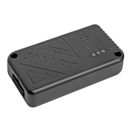
Page 7: Appearance Of The Device
1.5 Appearance of the device On the front part of the device unit (figure 1) is located: 14-pin connector of Microfit-14 type for connection of power supply, digital and analog sensors and control lines. On the side of the device unit (figure 2) is located: ... -
Page 8: Standard Equipment Set
1.6 Standard equipment set Tab. 2 Version of complete set № Name Number of pieces Device unit 14-pin connector of Microfit-14 with two power wires Cable set of 5 installation wires Interface cable with MiniUSB connector Passport Package Figure 4. 14-pin connector of Microfit-14 Figure 5. - Page 9 Figure 7. Fuel level sensor Figure 8. External LED The manufacturer reserves the right to complete the devices with equipment whose set, appearance and characteristics differ from those shown in the figures.
-
Page 10: Device Components
1.7. Device components The device consists of the following elements (see figures 9-12): 1) front cover; 2) fixing hole; 3) system LED indicator; 4) GSM LED indicator; 5) GLONASS / GPS LED indicator; 6) 14 pin connector; 7) MiniUSB connector; 8) SIM-card 1 ejector holder;... - Page 11 Figure. 11 Figure. 12...
-
Page 12: Device Interface Connector
1.8 Device interface connector Figure 13. System 14-pin interface connector 1 - Power “Plus” (+ U 2 – “Ground” (GND) 3 - Universal input 1 (UIN1) 4 - Universal input 2 (UIN2) 5 - Universal input 3 (UIN3) 6 – Output 1 "open collector" (OUT1) 7 –... -
Page 13: Connection Of The Device
2. CONNECTION OF THE DEVICE 2.1 Installation Before the system installation, first of all, it is necessary to determine the type and number of the connecting sensors, the identification system and other additional equipment. It is also necessary to be sure that all the additional equipment connected to the terminal are operable. -
Page 14: Sim-Card Installation And Operation
2.2 SIM-card installation and operation The device supports using of one SIM-card. The SIM card (external) installation is carried out without the use of special tools. Figure 15. SIM-card installation to the device Remove the SIM card holder from the device by pressing the yellow ejector button with a pen or a pencil. Place the SIM card in the holder with the gold contacts facing out. -
Page 15: Universal Inputs Connection
2.4 Universal inputs connection 2.4.1 Analog sensors connection The device allows to measure the voltage applied to the inputs in the range of 0 ... 31 V. When connecting analog FLS or other sensors for which the output voltage has to be monitored, the voltage measurement profile must be set in the inputs setting. -
Page 16: Pulse Frequency Sensors Connection
Profiles "Discrete NC+" and "Discrete NO+" allow to work with sensors, which, when turned on or off, close the input to “+” supply voltage. CPU_adc Figure 20. Connection of normally open (NO+) sensors CPU_adc Figure 21. Connection of normally closed (NC+) sensors Note: It is recommended to connect one of the universal input (usually UIN1) to the vehicle ignition line and make the appropriate setting in the configuration. -
Page 17: Built-In Accelerometer
or calculate the pulses. The connection diagram or frequency sensors, the output of which is implemented according to the “open collector” (OC) circuit with pull-up resistor is as follows: CPU_adc Figure 23. Connection of sensors with an “OC” type output circuit with a pull-up resistor in the sensor When pulse flow meters with a reed sensor is connected, one contact of which is connected to the “ground”, it is necessary to use an external pull-up resistor. - Page 18 Buzzer without built-in generator can be connected only to OUT1, because only this line has opportunity to modulate the control signal for the buzzer. Buzzer with built-in generator can be connected to any output. Connection diagrams for buzzer with build-in generator and for buzzer without build-in generator have no difference.
- Page 19 In order to connect car sirens without an additional control input, the inclusion of which is carried out by applying the supply voltage, it is necessary to use an additional relay, since the current consumed by such a siren may exceed the maximum allowable value for the output of the device.
- Page 20 Fuse Diode 1N4007 Fuse (1A) External device Car battery «GND» «GND» Figure 30. Connection diagram of the relay to the outputs of the device OUT1 and OUT2...
-
Page 21: Led Indication
3. LED INDICATION In order to display the operation modes and the current state of the system, three LEDs on the device case are used: SYS, GSM and NAV. The SYS system LED indicates the current status of the device. This LED indicates an alarm state if an alert is sent to subscribers by SMS, or an input is in the activated state.
Need help?
Do you have a question about the SMART S-2420 and is the answer not in the manual?
Questions and answers