
Related Manuals for NAVTELECOM SIGNAL S-2654


Summary of Contents for NAVTELECOM SIGNAL S-2654
- Page 1 GPS/GLONASS TRACKING EQUIPMENT SIGNAL S-2654 Operations manual Installation and connection of the device v1.0 MOSCOW 2020...
- Page 2 Customers are strongly advised to study this document carefully before the installation and operation of the device. Navtelecom LLC is interested in constantly improvement of the manufactured products quality. Please, contact our technical support by email address: support@navtelecom.ru should you have any questions or problems with the device.
-
Page 3: Table Of Contents
ONTENTS ..........................2 ONTENTS 1. BASIC CHARACTERISTICS ....................3 1.1 Purpose of the system ....................3 1.2 System tasks ......................... 3 1.3 Operational principles ....................3 1.4 Basic technical characteristics ..................4 1.5 Appearance of the device ....................9 1.6 Standard equipment set ....................10 1.7. -
Page 4: Basic Characteristics
1. BASIC CHARACTERISTICS 1.1 Purpose of the system The equipment is a GPS-GSM/UMTS Based Vehicle Tracking System. It is allowed to use the following terms in relation to this device: “system”, “product”, “equipment”, “device” “terminal”, “tracker”. The system is designed for: ... -
Page 5: Basic Technical Characteristics
1.4 Basic technical characteristics Tab 1 S-2654 GSM/GPRS/Bluetooth 3G modem GSM (GPRS) 900, 1800 GSM frequency bands UMTS (HSPA) 900, 1200 IP-stack protocols TCP, UDP Class 3 (0,25 W, 24 dBm) UMTS Transmitter power Maximum speed of data transfer/reception, Mb/s 5,76/7,2 SIM card holder 1 external with ejector (Molex), miniSIM... - Page 6 Working range with frequency fuel level sensors, Hz 1 – 3000 Up to 6 Number of analog inputs, configured as discrete (as a part of universal) Measuring range by inputs, set up as analog, V 0…31 Built-in pull-up resistor for discrete inputs Outputs Number of outputs of the “open collector”...
- Page 7 Number of servers (IP addresses) for synchronous receiving of telemetric data Sending telemetry data to the server repeatedly by SMS or GPRS request for the period Output of user and debug logs from GSM modem, GPS receiver and interfaces Data transferring in TCP and UDP The number of subscribers for SMS-alert Functionality EcoDriving function...
- Page 8 BLE, TECHNOTON DUT-E, GL-TV) Bluetooth connection for up to 4 wireless temperature and humidity sensors (ADM31, ESCORT TL-BLE) Bluetooth connection for ADM32 wireless tilt angel sensors Bluetooth connection for TECHNOTON GNOM DDE wireless axle load sensors Bluetooth connection for TECHNOTON DFM wireless fuel level sensor Bluetooth connection for ELM327 diagnostic adapter Transparent mode Unloading of ddd-files from «Shtrikh», «Mercuriy», «VDO Continental»,...
- Page 9 Interface connectors Microfit-14, Microfit-6, Microfit-4 Enclosure material ABS plastic Enclosure protection level IP54 Intrusion detector Device dimensions with connectors, mm 105х78х20,5 Device weight, kg 0,087 - Optional. - If maximum operating voltage is exceeded the power protection is activated. The device continues to work, but is powered by the battery (if available).
-
Page 10: Appearance Of The Device
1.5 Appearance of the device On the front part of the device unit (figure 1) is located: 14-pin connector of Microfit-14 type for connection of power supply, digital and analog sensors and control lines. 6-pin connector of Microfit-6 type with leads of CAN bus interface, RS-485 interface and RS-232 interface; ... -
Page 11: Standard Equipment Set
1.6 Standard equipment set Tab. 2 Version of complete set № Name Number of pieces SIGNAL device unit GLONASS/GPS-antenna GSM-antenna Fuse 1 А Fuse holder 14-pin connector of Microfit-14 with two power wires 6-contact connector of Microfit-6 type 4-contact connector of Microfit-4 type Cable set of 10 installation wires Passport Interface cable with MiniUSB connector... - Page 12 Figure 7. 14-pin connector of Microfit-14 type with power supply wires Figure 8. 6-pin connector of Microfit-6 type Figure 9. 4-pin connector of Microfit-4 type Figure 10. Interface cable with MiniUSB connector Some cases may require connection of additional equipment not included in the standard equipment set, for example: ...
- Page 13 Figure 11. Fuel level sensor Figure 12. Tachograph Figure 13. External LED Figure 14. Temperature sensor...
- Page 14 Figure 15. Tangent G-2500 Figure 16. TouchMemory contact key reader The manufacturer reserves the right to complete the devices with equipment whose set, appearance and characteristics differ from those shown in the pictures.
-
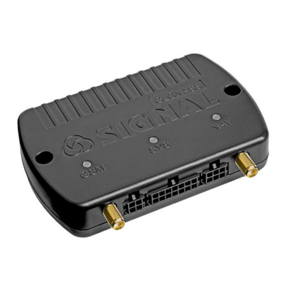
Page 15: Device Components
1.7. Device components The device consists of the following elements (see Figure 17-20): 1) front cover; 2) GSM LED indicator; 3) system LED indicator; 4) GLONASS / GPS LED indicator; 5) GSM antenna connector; 6) GLONASS/GPS antenna connector; 7) fixing hole; 8) 4-pin connector;... - Page 16 Figure 19 Figure 20...
-
Page 17: Device Interface Connector
1.8 Device interface connector Figure 21. System connectors Microfit-14, Microfit-6, Microfit-4 Microfit-14 connector: 1 - Power “Plus” (+ U 2 – “Ground” (GND) 3 - 1-Wire Interface Line (iBUT) 4 - Universal input 1 (UIN1) 5 - Universal input 2 (UIN2) 6 - Universal input 3 (UIN3) 7 –... - Page 18 Microfit-6 connector 1 - CAN interface line (CANL) 2 - RS-485 interface line (RS-485B (-)) 3 - RS-232 Interface Line (RS-232RX) 4 - CAN interface line (CANL) 5 - RS-485 interface line (RS-485A (+)) 6 - RS-232 Interface Line (RS-232TX) The digital interface RS-232 is designed for a connection of various devices transmitting and receiving information on this interface for example, a fuel level sensor, CAN bus adapter, tachographs, RFID, MODBUS devices, etc.
-
Page 19: Device Connection
2. DEVICE CONNECTION 2.1 Installation Before the system installation, first of all, it is necessary to determine the type and number of the connecting sensors, the identification system and other additional equipment. It is also necessary to be sure that all the additional equipment connected to the terminal are operable. - Page 20 Remove the SIM card holder from the device by pressing the yellow ejector button with a pen or a pencil. Place the SIM card in the holder with the gold contacts facing out. Carefully insert the holder along with the SIM card back into the device.
-
Page 21: Gsm- And Glonass/Gps Antennas Connection
2.3 GSM- and GLONASS/GPS antennas connection Connect the GSM- and GLONASS/GPS antennas as shown in the figure. The GSM antenna connector is below the GSM LED and the GLONASS/GPS antenna connector is below the NAV LED. Place the navigation antenna in a place that is most open for the view of the upper hemisphere (for the best "visibility"... -
Page 22: Universal Inputs Connection
When the system operates only from the built-in battery, the digital interfaces CAN and 1-Wire (IButton) do not function due to insufficient voltage. Power supply from the built-in battery is sufficient for operation of universal inputs, RS-232 and RS-485 interfaces, built-in accelerometer, GSM modem, GLONASS / GPS receiver and for the implementation of control outputs. - Page 23 when they are turned on or off. Note: With these profiles voltage is applied to the input through the built-in pull-up resistor Rpu. This allows not to use an external "pull-up" resistor when operating with sensors which operates on "-" (by "ground"). CPU_pull-up CPU_adc Figure 28.
- Page 24 CPU_pull-up CPU_adc Figure 30. Connection of normally open (NO+) sensors CPU_pull-up CPU_adc Figure 31. Connection of normally closed (NC+) sensors Note: It is recommended to connect one of the universal input (usually UIN1) to the vehicle ignition line and make the appropriate setting in the configuration. However, such connection is not mandatory. In addition to the source of notifications about turning on and turning off events, the input is used in coordinate processing algorithms (for example, when they are averaged at parking lots), energy saving, when calculating engine hours and in some other device algorithms.
-
Page 25: Pulse Frequency Sensors Connection
Fuse (1А) Alarm «-» «+» button Ignition switch Car battery «GND» UIN1 «GND» Figure 32. Connection of the ignition lock and alarm button Digital inputs are configured in the “Input lines” tab of the NTC Configurator program. 2.5.3 Pulse frequency sensors connection Сonnecting frequency or pulse sensors, it is necessary to consider how the output signal is generated in these sensors. -
Page 26: Built-In Accelerometer
CPU_pull-up CPU_adc Figure 34. Connection of flow meters with a reed sensor 2.6 Built-in accelerometer There are virtual sensors based on the built-in accelerometer (three-axis acceleration sensor): soft and strong impact sensors, displacement sensor and tilt sensor in the device. They can be used for alerts as well as external lines. - Page 27 Fuse Buzzer (1А) Car battery «GND» Figure 35. Connection diagram of buzzer It is possible to connect LED for indication of device operation mode and security mode state. If the power source is vehicle’s on-board network, the LED must be connected through current-limiting resistor. Such resistor is already installed inside the lamp in the automotive LED lamps.
- Page 28 In order to connect car sirens without an additional control input, the inclusion of which is carried out by applying the supply voltage, it is necessary to use an additional relay, since the current consumed by such a siren may exceed the maximum allowable value for the output of the device. The use of an additional relay is necessary for any load that can consume more than 500 mA.
-
Page 29: 1-Wire Informational Interface (Ibutton) Connection
Fuse Diode 1N4007 Fuse (1A) «-» «+» External device Car battery «GND» «GND» Figure 40. Connection diagram of the relay to the outputs of the device OUT1-OUT4 2.8 1-Wire informational interface (IButton) connection 1-Wire controller interface (IButton) allows to connect up to four digital sensors like DS18S20 (DS18B20) to the device, and it can also operate with DS1990 keys or key / card readers that emulate DS1990 keys via interface 1- Wire. - Page 30 Figure 44. Appearance of Proximity-cards and keyfobs and possible variants of their readers The terminal has the ability to connect temperature sensors to the 1-Wire interface using a two-wire circuit with “parasitic” power. Power is supplied through the same wire as the signal, therefore: the connection is made by two wires connected to the connector pins of the GND device (“ground”) and IBUT 1-Wire (signal and power).
-
Page 31: Amplifier Connection For Voice Information
telematics server (separate packet with this information). Digital temperature sensor codes, keys, maps and keyfobs of the identification systems can be read in the NTC Configurator program in the “Telemetry” window with external power connected to the device. 2.9 Amplifier connection for voice information The devices have the "Autoinformer"... - Page 32 CAN H 9 10 11 12 13 14 15 16 CAN L Fuse (1А) «GND» Car battery Figure 47. Connection diagram to OBD-II In some vehicles it is necessary to search for the needed bus in the wiring which goes to the dashboard, to the control controller or in other places.
-
Page 33: Rs-232 Interface Connection
CAN bus adapter that has several CAN interfaces. Attention! “Navtelecom” LLC is not responsible for malfunctions connected with the vehicle equipment when the device was directly connected to the vehicle's CAN bus without using contactless readers, as well as when it is connected to the OBDII connector in active mode. -
Page 34: Rs-485 Interface Connection
Sensors Tx RS232 Sensors Rx Devices Tx Devices Rx Fuse (1A) «-» «+» «GND» Car battery Figure 50. Connection diagram for fuel level sensor by RS-232 interface to the device Periodic data output mode must be enabled in the sensor and the network address and data transfer rate must coincide with those which are programmed in the device itself. -
Page 35: Speaker And Microphone Connection
In the fuel sensor, the periodic data output mode must be turned off, and the network address and data transfer rate must match the corresponding programmed parameters in the device itself. 2.13 Speaker and microphone connection The speaker output is differential, but the polarity of its connection can be ignored, unless it is not specified by the speaker manufacturer. -
Page 36: Led Indication
3. LED INDICATION In order to display the operation modes and the current state of the system, three LEDs on the device case are used: SYS, GSM and NAV. The SYS system LED indicates the current status of the device. This LED indicates an alarm state if an alert is sent to subscribers by SMS, or an input is in the activated state.
Need help?
Do you have a question about the SIGNAL S-2654 and is the answer not in the manual?
Questions and answers