Table of Contents
Advertisement
Quick Links
AMP Weld Smart E Controller
Operation Manual
EPP-4024-7/22
For more information: te.com/energy
Tyco Electronics Raychem GmbH
a TE Connectivity Ltd. Company
Finsinger Feld 1
85521 Ottobrunn/Munich, Germany
Tel:
+49-89-6089-0
Fax:
+49-89-6096-345
The Information contained in these installation instructions is for use only by installers trained to make electrical power installations and is
intended to describe the correct method of installation for this product. However, TE Connectivity has no control over the field conditions which
influence product installation.
It is the user's responsibility to determine the suitability of the installation method in the user's field conditions.
TE Connectivity's only obligations are those in TE Connectivity's standard Conditions of Sale for this product and in no case will TE Connectivity
be liable for any other incidental, indirect or consequential damages arising from the use or misuse of the products.
Raychem, TE, TE Connectivity and TE connectivity (logo) are trademarks. © 2022 TE Connectivity. All Rights Reserved.
Please dispose of all waste according to
environmental regulations.
Advertisement
Table of Contents

Related Manuals for TE Connectivity EPP-4024-7/22


Summary of Contents for TE Connectivity EPP-4024-7/22
- Page 1 It is the user’s responsibility to determine the suitability of the installation method in the user’s field conditions. TE Connectivity’s only obligations are those in TE Connectivity’s standard Conditions of Sale for this product and in no case will TE Connectivity be liable for any other incidental, indirect or consequential damages arising from the use or misuse of the products.
-
Page 2: Table Of Contents
3. What’s in the Box ................................4 4. Technical Specifications ..............................5 5. Product Features ................................6 6. Operation..................................7 6.1 Connect the Controller .............................. 7 6.2 Prepare for Weld ............................... 7 6.3 Weld Operation ................................. 7 EPP-4024-7/22 • 2/12... -
Page 3: Safety
RoHS Compliance Statement Based on the certificate of compliance provided by our suppliers, and to the best of our knowledge, TE Connectivity designates that the parts used in the AMP Weld Controller are compliant with RoHS (Restriction of Hazardous Substance) directive 2011/65/EU amended with directive 2015/863/EU as set forth by the European Union. -
Page 4: Introduction
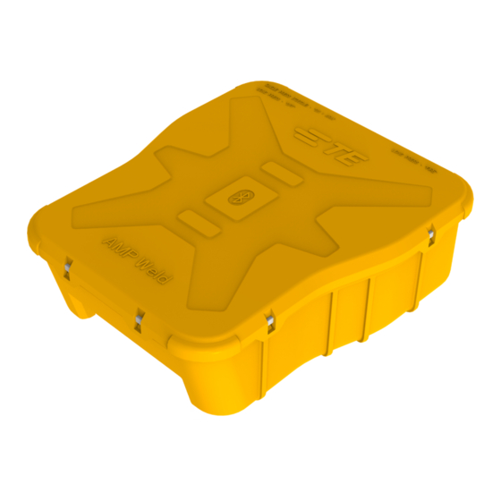
3. What’s in the Box The AMP Weld Controller kit consists of the following components: Figure 1: AMP Weld Controller Kit 1. Box / Carry case 2415600 2. Connection Harness 2389716 3. AMP Weld Controller 2388292 4. Battery, 18V 2415598 EPP-4024-7/22 • 4/12... -
Page 5: Technical Specifications
4.1 AMP Weld Application - Minimum Requirements Table 2: AMP Weld Application requirements System specifications Properties Android 4.4.4 (KitKat) or later Operating System iOS 12 or later 1GB to 2GB Internal Memory 2GB to 8GB Bluetooth 5.0 or later EPP-4024-7/22 • 5/12... -
Page 6: Product Features
The power switch is a push button with green LED indicator which is used to power ON, ARM and power OFF (by long press) the controller. 5.2 Fire Switch The fire switch is a push button with red LED indicator which is used to fire or ignite tungsten. EPP-4024-7/22 • 6/12... -
Page 7: Operation
1. Connect the controller to the battery. Refer to 6.1 Connect the Controller. 2. Prepare the controller for weld. Refer to 6.2 Prepare for Weld. 3. Press the power switch (1) to turn ON the controller. When the controller is ON, the green LED indicator will illuminate. EPP-4024-7/22 • 7/12... - Page 8 6. Select the controller unit (TE-XXXXXXXXXX) from the scan list to pair with mobile device. Alternatively, you can also pair the controller using the Scan QR code button and then scanning the QR code at the back of the controller. EPP-4024-7/22 • 8/12...
- Page 9 The pairing code is the last six digits of the TE ID imprinted on the product. For example, if the TE ID is TE-0123456789 then the pairing code is 456789. 9. After successful pairing, the app should show the controller device ID on controller info screen. EPP-4024-7/22 • 9/12...
- Page 10 A ‘Fire completed’ notification should pop-up in application. NOTE If the fire operation is initated without connecting the load, then you will see a error message and the controller will go back to ready to arm state. EPP-4024-7/22 • 10/12...
- Page 11 12. Close the Notification, and the app will go back to ARM Page. 13. Click on TURN OFF button, to turn OFF the controller. When the controller is turned OFF, the power switch LED (green) indicator should go OFF. EPP-4024-7/22 • 11/12...
- Page 12 EPP-4024-7/22 • 12/12...
Need help?
Do you have a question about the EPP-4024-7/22 and is the answer not in the manual?
Questions and answers