Table of Contents

Related Manuals for Panasonic AG-CX10P


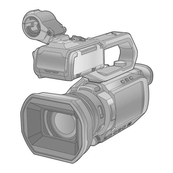
Summary of Contents for Panasonic AG-CX10P
- Page 1 Order No.VM2002003CE Memory Card Camera-Recorder AG-CX10P Model No. AG-CX10E AG-CX10EN AG-CX10ED AG-CX10AN AG-CX98MC Colour (K)...Black Type © Panasonic Corporation 2020 Unauthorized copying and distribution is a violation of law.
-
Page 2: Table Of Contents
Table of Contents Page Page 1. Safety Precautions............3 6.7. Touch Panel Calibration............. 35 1.1. General Guidelines..............3 7. Service Fixture & Tools..........36 8. Disassembly and Assembly Instructions..... 37 1.2. Leakage Current Cold Check..........3 1.3. Leakage Current Hot Check (See Figure. 1)......3 8.1. -
Page 3: Safety Precautions
1 Safety Precautions 1.1 General Guidelines 1. IMPORTANT SAFETY NOTICE There are special components used in this equipment which are important for safety. These parts are marked by the Schematic Diagrams, Circuit Board Layout, Exploded Views and Replacement Parts List. It is essential that these critical parts should be replaced with manufacturer’s specified parts to prevent X-RADIATION, shock, fire, or other hazards. -
Page 4: Warning
2 Warning 2.1 Prevention of Electrostatic Discharge (ESD) to Electrostatically Sensitive (ES) Devices Some semiconductor (solid state) devices can be damaged easily by static electricity. Such components commonly are called Electrostatically Sensitive (ES) Devices. Examples of typical ES devices are integrated circuits and some field-effect transistors and semiconductor "chip"... -
Page 5: Caution For Ac Cord (For E/En)
If you lose the fuse cover, the plug must not be used until a replacement cover is obtained. A replacement fuse cover can be purchased from your local Panasonic Dealer. If the fitted moulded plug is unsuitable for the socket outlet in your home then the fuse should be removed and the plug cut off and disposed of safety. - Page 6 2.3.2.2 Before Use • Remove the Connector Cover as follows. 2.3.2.3 How to Replace the Fuse 1. Remove the Fuse Cover with a screwdriver. 2. Replace the fuse and attach the Fuse cover. - 6 -...
-
Page 7: How To Replace The Lithium Battery
2.4 How to Replace the Lithium Battery 2.4.1 Replacement Procedure 1. Remove the ZOOM Unit. (Refer to Disassembly Procedures.) 2. Remove the Lithium battery (Ref. No. “B6701” at foil side of ZOOM P.C.B.) and then replace it into new one. NOTE: This Lithium battery is a critical component. It must never be subjected to excessive heat or discharge. -
Page 8: Service Navigation
3 Service Navigation 3.1 Introduction This service manual contains technical information, which allow service personnel’s to understand and service this model. Please place orders using the parts list and not the drawing reference numbers. If the circuit is changed or modified, the information will be followed by service manual to be controlled with original service manual. -
Page 9: How To Define The Model Suffix (Ntsc Or Pal Model)
3.3 How to Define the Model Suffix (NTSC or PAL model) There are five kinds of AG-CX10, CX98. • a) AG-CX10P • b) AG-CX10E/ED • c) AG-CX10EN • d) AG-CX10AN • e) AG-CX98MC What is the difference is that the “INITIAL SETTING” data which is stored in Flash ROM mounted on Main P.C.B.. -
Page 10: Specifications
4 Specifications The following specification is for AG-CX7/8/10EN. Some specifications may differ depending on model suffix. The page number in this chapter does not show the page number of this service manual. - 10 -... - Page 11 - 11 -...
- Page 12 - 12 -...
- Page 13 - 13 -...
- Page 14 - 14 -...
- Page 15 - 15 -...
- Page 16 - 16 -...
- Page 17 - 17 -...
- Page 18 - 18 -...
-
Page 19: Location Of Controls And Components
5 Location of Controls and Components AG-CX7_CX8_CX10-DVQX2032_eng.book 21 ページ 2020年1月6日 月曜日 午後2時31分 The following description is for AG-CX7/8/10EN. Some descriptions may differ depending on model suffix. Description of parts The page number in this chapter does not show the page number of this service manual. Description of parts Main unit ≥... - Page 20 Description of parts Card slot 1 (l 36) <DISP/MODE CHK> button A slot for the memory card. Switches display/hide of information Card 1 access lamp other than the time counter, time stamp, Indicates the access status for recording zebra pattern, and marker. and playback of the memory card Press and hold the button to display inserted in card slot 1.
- Page 21 Description of parts <GAIN> button (l 48) <EXIT> button Selects the method for adjusting screen Returns to one level higher when the brightness. menu is displayed. Pressing the <EXIT> <IRIS> button (l 45) button without confirming the setting Selects the method for adjustment of the value will not reflect the change in the lens stop.
- Page 22 Description of parts <REMOTE> terminal Tripod mounting holes Connects the remote control unit Attach the tripod. (bottom) (commercially-available) to control some ≥Mounting hole size functions remotely. j 1/4-20 UNC (screw length 5.5 mm USB terminal or shorter) Connect to a computer with the USB2.0 ≥Attaching a tripod with a screw length cable to transfer data.
- Page 23 Description of parts LCD monitor 180° 90° 90° 53 54 Built-in microphone <USER5> button This is the built-in stereo microphone Used as a USER button (USER5). <L>/<R>. ≥[REC CHECK] is set at the time of Accessory shoe (on the main unit) purchase.
- Page 24 Description of parts Handle unit (supplied) 14 13 A With a microphone holder attached Handle <INPUT1> switch Switches audio input signals connected Microphone holder mounting section to the <INPUT 1> terminal. (l 32) CH1 SELECT switch Attaches the supplied microphone Selects the audio to be recorded on holder with the microphone holder audio channel 1.
- Page 25 Description of parts <CH1> switch Handle unit mounting screw (l 32) Selects how the recording level for audio Secures the handle unit to the main unit. channel 1 is adjusted. <AUDIO LEVEL CH1> dial Adjust the recording level of audio channel 1.
-
Page 26: Service Mode
6 Service Mode Indication method of the service menu 1. Set the power switch to ON. 2. Press the “O.I.S./ USER 3”button, “WHITE BAL”button and “Zoom Lever”to W side for more than 3 seconds until the top screen of the Service Mode Menu is displayed. Service mode menu NOTE: Do not use the service mode except the table of service mode menu above. -
Page 27: Model/Destination Settings
6.1 Model/Destination Settings Touch the [ 2 ] of LCD, select model/destination settings. Operation procedure Function description • Change the Model/Destination Display the lists of model/distination which the unit can be changed, if a shipment setup is finished. Therefore in some cases, the model/destination that is currently set is only displayed. End method of operation •... -
Page 28: Usage Time Display
6.2 Usage time display Touch the [4] of LCD and select usage time display. Operation procedure Indication contents • Function to display power-on usage time, MOS sensor usage time, recording time, error history information, etc. • Error history information can be backed up to an SD card. - 28 -... - Page 29 End method of operation • Touch the of LCD and then press the power button to turn off the power. - 29 -...
-
Page 30: Power On Self Check Result Display
6.3 Power ON Self Check Result Display Touch the [ 5 ] of LCD, select Power ON self check result display. Operation procedure Indication contents • Power ON self check result display Function to diagnose correct function of the device and interface between devices result display. Display the following communication test result. -
Page 31: Usage Time Reset
6.4 Usage time reset Touch the [10] of LCD and select usage time reset. Operation procedure Indication contents • Function that resets the operating time of the power-on state, the operating time of the MOS sensor, the recording time, the operating time of the zoom switch, etc. End method of operation •... -
Page 32: Adjustment Function For The Service
6.5 Adjustment function for the Service Touch the [14] of LCD, select the adjustment function for the service. Operation procedure (before the adjustment starts) Function description For the adjustment function of servicing, the required setup and adjustment shouid be performed when servicing. For a detailed content, such as the adjustment procedure, refer to “9 Measurements and Adjustments”. -
Page 33: Restore The Backed Up Adjustment Data
6.6 Restore the backed up adjustment data Touch the [15] of LCD, select restoring the backed up adjustment data from SD card to the unit. Operation procedure Function description Restore the adjustment data to new or repaired Main P.C.B. from SD card that the data backed up from original Main P.C.B. before repairs or replacement. - Page 34 Restoring procedure End method of operation • Set the power switch to OFF and terminate restoring the backed up adjustment data. - 34 -...
-
Page 35: Touch Panel Calibration
6.7 Touch Panel Calibration Touch the [16] of LCD, select the calibration of touch panel. Operation procedure Function description Calibrate the touch positions of the touch panel. End method of operation • The cut off of battery connection / AC power connection leads the adjustment of touch panel to end. - 35 -... -
Page 36: Service Fixture & Tools
7 Service Fixture & Tools Refer to the jig parts numbers listed in “9. Measurements and Adjustments” for jigs and tools. And also, inspection of various boards should be performed using existing flexible cables and cables. No service extension cable is required. - 36 -... -
Page 37: Disassembly And Assembly Instructions
8 Disassembly and Assembly Instructions 8.1 Camera body 8.1.1 Disassembly Flow Chart for the Unit This is a disassembling chart. When assembling, perform this chart conversely. - 37 -... - Page 38 8.1.2 PCB Location - 38 -...
- Page 39 8.1.3 Disassembly Procedure for the Unit - 39 -...
- Page 40 - 40 -...
- Page 41 - 41 -...
- Page 42 8.1.3.1 Precautions when disassembling/ assembling 1. Rerove the Handle Unit from the Main Body. 2. When servicing and reassembling, remove the memory card and battery pack from the unit. 3. Do not reuse the screws tightened to metal materials. New screws must be used when assembling. - 42 -...
- Page 43 8.1.3.2 Removal of the Lens Hood Unit (Fig.1) 8.1.3.3 Removal of the Side Case L Unit (Fig.2) - 43 -...
- Page 44 (Fig.3) 8.1.3.4 Removal of the Jack P.C.B. (Fig.4) - 44 -...
- Page 45 8.1.3.5 Removal of the Rear Case Unit (Fig.5) - 45 -...
- Page 46 8.1.3.6 Removal of the Fan Duct Unit (Fig.6) - 46 -...
- Page 47 8.1.3.7 Removal of the WIFI SS P.C.B. (Fig.7) - 47 -...
- Page 48 8.1.3.8 Removal of the DC Motor unit (Fig.8) - 48 -...
- Page 49 8.1.3.9 Removal of the Side Case R Unit (Fig.9) - 49 -...
- Page 50 (Fig.10) - 50 -...
- Page 51 8.1.3.10 Removal of the Top Case Unit (Fig.11) - 51 -...
- Page 52 (Fig.12) 8.1.3.11 Removal of the MF Unit & Lens Frame Unit (Fig.13) - 52 -...
- Page 53 (Fig.14) - 53 -...
- Page 54 8.1.3.12 Removal of the EVF Case Unit (Fig.15) - 54 -...
- Page 55 8.1.3.13 Removal of the SD Frame, SD P.C.B. (Fig.16) 8.1.3.14 Removal of the Main P.C.B. (Fig.17) - 55 -...
- Page 56 (Fig.18) 8.1.3.15 Removal of the SDI Holder Unit (Fig.19) - 56 -...
- Page 57 8.1.3.16 Removal of the Main Frame (Fig.20) - 57 -...
- Page 58 8.1.3.17 Removal of the Battery Case Unit (Fig.21) (Fig.22) - 58 -...
- Page 59 8.1.3.18 Removal of the MF Unit (Fig.23) (Fig.24) - 59 -...
- Page 60 8.1.3.19 Removal of the Camera Lens Unit (Fig.25) (Fig.26) - 60 -...
- Page 61 8.1.3.20 Removal of the LCD Relay P.C.B. (Fig.27) - 61 -...
- Page 62 8.1.3.21 Removal of the MIC P.C.B. Unit (Fig.28) 8.1.3.22 Removal of the Top Inner Case Unit (Fig.29) - 62 -...
- Page 63 (Fig.30) 8.1.3.23 Removal of the Top Frame Unit, Top OP P.C.B. (Fig.31) - 63 -...
- Page 64 (Fig.32) - 64 -...
- Page 65 8.1.3.24 Removal of the Zoom Unit (Fig.33) - 65 -...
- Page 66 8.1.3.25 Removal of the R Frame Front, Menu OP P.C.B., LCD Unit (Fig.34) - 66 -...
- Page 67 (Fig.35) - 67 -...
- Page 68 (Fig.36) - 68 -...
- Page 69 8.1.3.26 Removal of the Menu OP Button, Kurupon Unit (Fig.37) 8.1.3.27 Removal of the R Frame Rear, Side R OP P.C.B. (Fig.38) - 69 -...
- Page 70 (Fig.39) - 70 -...
- Page 71 8.1.3.28 Removal of the R OP Button, Shutter Button, Auto MNL Lever, SD Door Unit, SD LED Panel (Fig.40) 8.1.3.29 Removal of the R OP Earth Plate, Speaker (Fig.41) - 71 -...
- Page 72 8.1.3.30 Removal of the LCD Hinge Unit (Fig.42) - 72 -...
- Page 73 (Fig.43) 8.1.3.31 Removal of the LCD Plate Unit (Fig.44) - 73 -...
- Page 74 8.1.3.32 Removal of the Grip Belt (Fig.45) - 74 -...
- Page 75 (Fig.46) - 75 -...
- Page 76 8.1.3.33 Removal of the 2nd Stepping Motor (Fig.47) - 76 -...
- Page 77 8.1.3.34 Removal of the 3rd Stepping Motor (Fig.48) - 77 -...
- Page 78 8.1.3.35 Removal of the 4th Stepping Motor (Fig.49) - 78 -...
-
Page 79: Handle Unit
NOTE: (After Assembling) Make sure to confirm the following points after assembling. • The screw is tightened enough. • Installing conditions are fine. (No distortion, no abnormalspace.) • No dust and/or dirt on image sensor surface. • LCD image is fine. (No dust and/or dirt on it, and no gradient images.) 8.2 Handle Unit 8.2.1 Disassembly Flow Chart This is a disassembling chart. - Page 80 8.2.2 P.C.B. Location - 80 -...
- Page 81 8.2.3 Disassembly Procedure for the Unit - 81 -...
- Page 82 8.2.3.1 Precautions when disassembling/ assembling • Do not reuse the screws tightened to metal materials. New screws must be used when assembling. 8.2.3.2 Removal of the Handle Side Case L Unit (Fig.H1) - 82 -...
- Page 83 8.2.3.3 Removal of the HA XLR P.C.B. Unit (Fig.H2) - 83 -...
- Page 84 8.2.3.4 Removal of the Handle Top Case 1 Unit (Fig.H3) 8.2.3.5 Removal of the HA Zoom P.C.B., Handle LED OP P.C.B. Unit (Fig.H4) - 84 -...
- Page 85 (Fig.H5) - 85 -...
- Page 86 8.2.3.6 Removal of the HA LED P.C.B., Handle LED Light Lens, Handle LED Light Cover (Fig.H6) - 86 -...
- Page 87 8.2.3.7 Removal of the Handle Side Case R Unit (Fig.H7) - 87 -...
- Page 88 8.2.3.8 Removal of the USB Cover, HA Connector P.C.B., Handle Bottom Cover B Unit (Fig.H8) - 88 -...
- Page 89 (Fig.H9) 8.2.3.9 Removal of the Tripod, Handle Grip (Fig.H10) - 89 -...
- Page 90 (Fig.H11) - 90 -...
- Page 91 8.2.3.10 Removal of the Handle Frame Piece Unit, HA Main P.C.B. (Fig.H12) - 91 -...
-
Page 92: Measurements And Adjustments
9 Measurements and Adjustments 9.1 Electric Adjustment • An exclusive jig is necessary for electric adjustment. • Connection and location method of the main unit and an exclusive adjustment jig are shown below. Figure of connection Figure of image when adjustment - 92 -... - Page 93 Part Number of jig - 93 -...
- Page 94 [Vignetting Adjutment Chart] + - 94 -...
- Page 95 9.1.1 Adjustment Items Adjustment item as follows. - 95 -...
- Page 96 9.1.2 Adjustment Procedure All adjustments except “Touch Panel Calibration”and “Factory Setting” performs using “14 Adjustment function for the service” in service mode menu. “Touch Panel Calibration” is performed using 16 of service mode menu and “Factory Setting” is performed using 1, of service mode menu.
- Page 97 [ Adjustment Procedure ] Adjustments and settings are performed following order: • Top Screen • Model Setting • Backup File Name • Adjust Data Backup • Checking Switches • Zoom Lever Adjustment • Camera Adjustment (Iris, Gyro, OIS) • Tracking Adjustment •...
- Page 98 - 98 -...
- Page 99 - 99 -...
- Page 100 - 100 -...
- Page 101 - 101 -...
- Page 102 - 102 -...
- Page 103 - 103 -...
- Page 104 - 104 -...
- Page 105 - 105 -...
- Page 106 - 106 -...
- Page 107 - 107 -...
- Page 108 - 108 -...
-
Page 109: Factory Setting
10 Factory Setting 10.1 How To Turn On The Factory Settings? 1. Set the power switch to ON. 2. Press the “O.I.S./ USER 3”button, “WHITE BAL”button and “Zoom Lever”to W side for more than 3 seconds until the top screen of the Service Mode Menu is displayed. 3. -
Page 110: What Is The Factory Settings
10.2 What Is The Factory Settings? The factory settings clean up and/or refresh the following settings. 1. Setting Values of menu. 2. Clear the time and date setting. 3. Zoom position (Wide end) 4. Initialize the Wi-Fi data settings. The shipment setting position of switches and lever: (After the factory settings, set the switches and lever as following table.) - 110 -... -
Page 111: Block Diagram
11 Block Diagram 11.1 Overall Block Diagram LENS(F1.8-4.0 24x) ZOOM/ MOS IMAGE HDMI FOCUS ND IR SENSOR TERMINAL IRIS MOTOR/ FILTER IC102 GATE IC IC4002 SIGNALCLOCK IC7202 GENERATOR Analog DIGITAL HEADPHONE ACCELEROMETER TERMINAL IC604,607 IC4001 IR FIL DRIVE/ AVIO ND DRIVE Analog SPEAKER IC601,602,603,605,606,609,614 LENS/OIS/IRIS/MOTOR DRIVE,... - Page 112 [ HANDLE UNIT ] IC6510,6511,6512 Q6605,6601,6602,6603,6604 DC-DC CONVERTER, REGULATOR, SWITCHING REGULATOR CONTROLLER AUDIO Analog IC6505,6506 Analog IC6504 INPUT1 MIC/MIX AMP MULTIPLEXER (XLR3 pin) Analog USB TERMINAL TO BODY UNIT (Type-C) AUDIO Analog IC6507 IC6508,6509 INPUT2 MIC/MIX AMP MULTIPLEXER (XLR3 pin) LED LIGHT IC6513 RESET...
-
Page 113: Wiring Connection Diagram
12 Wiring Connection Diagram 12.1 Interconnection Diagram ZOOM UNIT SPEAKER ZOOM SW TOP OP P.C.B. EVF UNIT (FOIL SIDE) EVF FPC GRIP ZOOM P.C.B. (FOIL SIDE) TOP OP FFC LCD MODULE A WIRED FFC LCD PLATE UNIT GRIP ZOOM FFC MONITOR P.C.B. (FOIL SIDE) SIDE R OP P.C.B. - Page 114 [ HANDLE UNIT ] HA LED P.C.B. (FOIL SIDE) LED FFC HA AUDIO OP P.C.B. HA XLR P.C.B. (COMPONENT SIDE) (FOIL SIDE) FP6502 PW XLR48V PW XLR48V MIC GND MIC GND XLR1 P XLR FFC XLR1 N XLR2 N XLR2 P MIC GND MIC GND XLR1 48V ON...
-
Page 115: Exploded View And Replacement Parts List
13 Exploded View and Replacement Parts List 13.1 Frame Parts Assembly B148 B153 B111 B154 B149 B112 B110 B114 B147 B145 201-2 B205 B206 B109 B207 B108 B128 201-1 B129 201-3 B131 B130 B204 B203 B115 B201 B144 B132 B202 B100 B146 B101 B102 B105... - Page 116 85-1 10-1 82-1 82-2 - 116 -...
- Page 117 - 117 -...
- Page 118 51-1 51-2 51-3 - 118 -...
-
Page 119: Handle Unit Parts Assembly
13.2 Handle Unit Parts Assembly B507 B504 B505 B503 B508 B506 B509 B585 B511 B576 B512 B575 B582 B510 B581 B584 B574 B571 B573 B583 B572 B533 B532 xx 551 B531 B517 B519 xx 554 B518 B516 B515 B534 B535 B514 B586 B537 B536... -
Page 120: Packing Parts Assembly
13.3 Packing Parts Assembly 321-1 - 120 -... -
Page 121: Casing Replacement Parts List
13.4 Casing Replacement Parts List Safety & mark - 121 -... - Page 122 Safety & mark - 122 -...
- Page 123 Safety & mark - 123 -...
- Page 124 Safety & mark - 124 -...
-
Page 125: Handle Unit Replacement Parts List
13.5 Handle Unit Replacement Parts List Safety & mark - 125 -... - Page 126 Safety & mark - 126 -...
-
Page 127: Packing Replacement Parts List
13.6 Packing Replacement Parts List Safety & mark CX10P CX10E CX10E 10AN - 127 -...
Need help?
Do you have a question about the AG-CX10P and is the answer not in the manual?
Questions and answers