Table of Contents
Advertisement
Quick Links
SERVICE
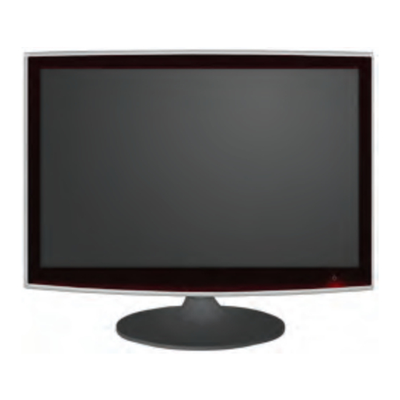
TFT-LCD Monitor
T220M / T200M
Refer to the service manual in the GSPN (see the rear cover) for the more information.
LCD-Monitor
Chassis
: LS22TDS / LS20TDS
Model
: T220M / T200M
Manual
1. Precautions
2. Product specifications
3. Disassembly and Reassemble
4. Troubleshooting
5. Exploded View & Part List
6. Wiring Diagram
7. Schematic Diagram
Contens
Advertisement
Table of Contents

Related Manuals for Samsung T220M


Summary of Contents for Samsung T220M
- Page 1 LCD-Monitor Chassis : LS22TDS / LS20TDS Model : T220M / T200M SERVICE Manual TFT-LCD Monitor Contens 1. Precautions 2. Product specifications 3. Disassembly and Reassemble 4. Troubleshooting 5. Exploded View & Part List 6. Wiring Diagram 7. Schematic Diagram T220M / T200M Refer to the service manual in the GSPN (see the rear cover) for the more information.
-
Page 2: Table Of Contents
Contents 1. Precautions ......................1-1 1-1. Safety Precautions ......................1-1 1-2. Servicing Precautions ..................... 1-2 1-3. Static Electricity Precautions ..................1-2 1-4. Installation Precautions ....................1-3 2. Product specifications .................... 2-1 2-1. Feature & Specifications ....................2-1 2-2. Spec Comparison to the Old Models ................2-3 2-3. - Page 3 GSPN (Global Service Partner Network) Area Web Site North America http://service.samsungportal.com Latin America http://latin.samsungportal.com http://cis.samsungportal.com Europe http://europe.samsungportal.com China http://china.samsungportal.com Asia http://asia.samsungportal.com Mideast & Africa http://mea.samsungportal.com © 2008 Samsung Electronics Co.,Ltd. This Service Manual is a property of Samsung Electronics Co.,Ltd. All rights reserved. Any unauthorized use of Manual can be punished under applicable Printed in Korea International and/or domestic law. P/N: BN82-00479A-00...
-
Page 4: Precautions
1. Precautions 1. Precautions 1-1. Safety Precautions Follow these safety, servicing and ESD precautions to prevent damage and to protect against potential hazards such as electrical shock. 1-1-1. Warnings For continued safety, do not attempt to modify the circuit board. Disconnect the AC power and DC power jack before servicing. -
Page 5: Servicing Precautions
1. Precautions 1-2. Servicing Precautions WARNING: An electrolytic capacitor installed with the wrong polarity might explode. Caution: Before servicing units covered by this service manual, read and follow the Safety Precautions section of this manual. Note: If unforeseen circumstances create conflict between the following servicing precautions and any of the safety precautions, always follow the safety precautions. -
Page 6: Installation Precautions
1. Precautions 1-4. Installation Precautions For safety reasons, more than two people are required for carrying the product. Keep the power cord away from any heat emitting devices, as a melted covering may cause fire or electric shock. Do not place the product in areas with poor ventilation such as a bookshelf or closet. The increased internal temperature may cause fire. - Page 7 1. Precautions Memo...
-
Page 8: Product Specifications
2. Product specifications 2. Product specifications 2-1. Feature & Specifications Model T220M / T200M Feature Supreme Digital Interface & Networking � - With a built-in with no particular set-top box and provides simple access with a single remote control. Excellent Picture Quality �... - Page 9 2. Product specifications Specifications Description Item T220M T200M Antenna Input 75Ω Sound Characteristic -MAX Internal speaker Out : Right : 3W / Left : 3W -BASS Control Range : -8 dB ~ + 8dB -TREBLE Control Range : -8 dB ~ +8 dB...
-
Page 10: Spec Comparison To The Old Models
2. Product specifications 2-2. Spec Comparison to the Old Models Model T220M / T200M Curie (225MD) Design Screen Size 20” / 22” 22” Frequency 30 ~ 81 kHz 30 ~ 81 kHz Horizontal 56 ~ 75 Hz 56 ~ 75 Hz... -
Page 11: Accessories
Description Ccde. No Remark Remote Control & BN59-00678A Batteries (AAA x 2) Power Cord 3903-000190 Stand Body BN96-07347D Samsung Electronics Service center Stand Base BN96-07345A D-Sub Cable BN39-00244G User’s Guide, Monitor Driver, BN96-07540A Natural Color Pro Software Cleaning Cloth BN63-01798A... -
Page 12: Disassembly And Assembly
3. Disassembly and Assembly 3. Disassembly and Assembly This section describes the disassembly and reassembly sequences for this monitor. Warning: As this monitor has parts that are sensitive to static electricity, be careful when handling them. 3-1. Disassembly Caution: 1. Turn the monitor off before beginning the disassembly process. 2. - Page 13 3. Disassembly and Assembly Description Photo Screws 3. Insert a flat screwdriver into the groove and then lift up and remove the cover. 4. After remove COVER-REAR, then disconnect SPEAKER , FUNCTION wire. 5. Disconnect LVDS cable from panel.
- Page 14 3. Disassembly and Assembly Description Photo Screws 6. After disconnecting SHIELD-LAMP of left side, disassemble lamp wire between panel and IP Board. 7. Remove 8 marked SCREW of left picture. Disconnect IP board. ※ Reassembly procedures are in the reverse order of disassembly procedures.
- Page 15 3. Disassembly and Assembly Description Photo Screws 9. Remove the IR module by tilting the left snap to the right. 10. Remove the LED module by sliding the snap designated in the right figure backwards. 11. Remove the two (2) screws and then remove the holders from the four (4) snaps designated in the right figure using the provided jig.
- Page 16 3. Disassembly and Assembly Description Photo Screws 12. Remove the two (2) connectors. Caution : Servicing is not supported for the PCB. ▶Assembly 13. The assembly is in the reverse order of the disassembly. 14. Connect the disassembled snap and the LED module again.
- Page 17 3. Disassembly and Assembly Memo...
- Page 18 5. Exploded View & Part List 5. Exploded View & Part List 5-1. LS20TDSSUMZD - Exploded View (T220M)
- Page 19 5. Exploded View & Part List 5-1-1. LS20TDSSUMZD - Parts List (T220M) Location No. Code No. Description & Specification Q’ty SA/SNA Remark M0006 BN96-08149G ASSY SHIELD P-COVER;LS20TD(ANALOG),SECC S.N.A M0013 BN96-07447H ASSY COVER P-REAR;LS20TD(ANALOG),PMMA AB M0014 BN94-01893R ASSY PCB MAIN;LS20TDSSU/ZB M0027 BN96-07345B ASSY STAND P-BASE;LS22TW,ABS HB PMMA,RD0...
- Page 20 5. Exploded View & Part List 5-2. LS20TDSSUMZD Parts List Service Bom (SA: SERVICE AVAILABLE, SNA: SERVICE NOT AVAILABLE) Level Location No. Code No. Description & Specification Q’ty SA/SNA Remark LS20TDSSUMZD T200M,WST1/S20A4-LTD,20,LCD-MO,BRAZIL M0001 BN90-01634H ASSY COVER FRONT;LS20TD_MFM,TOC,ROSE BLA S.N.A M0081 6006-001096 SCREW-TAPTITE;BH,+,WP,B,M4.0,L12,ZPC(BLK S.N.A...
- Page 21 6003-001086 SCREW-TAPTITE;BH,+,-,B,M3,L12,ZPC(BLK),S M0135 BN91-01517B ASSY LCD-PTZ;LS20MEW* S.N.A M0215 BN07-00374A LCD-PANEL;CLAA201WA04 M0112 BN91-02443C ASSY SHIELD;LS20TD_MFM,TOC,ANALOG S.N.A T0279 BN63-05063A COVER-JACK;T220M ANALOG,ABS + PC,HB,BK26 S.N.A M0090 BN96-08016A ASSY SHIELD P-LAMP;LS20TD(MFM),SPTE,T 0. S.N.A ...3 BN63-04401A SHIELD-LAMP;T(22W MFM),SPTE,T 0.3 S.N.A ...3 M0125 BN63-04772A SHIELD-PANEL;LS20TD,SPTE,0.3 S.N.A...
- Page 22 5. Exploded View & Part List Level Location No. Code No. Description & Specification Q’ty SA/SNA Remark ...3 CN330 3711-006715 HEADER-BOARD TO CABLE;BOX,4P,1R,2.5mm,AN S.N.A ...3 JA330 3722-002176 JACK-PHONE;7P/4C,SN,L-BLU,STRAIGHT ...3 CN3005 3722-002275 JACK-DIN;4P,SN,BLK,ANGLE ...3 CN2003 3722-002680 JACK-EAR PHONE;6P,NiSn,BLK,ANGLE ...3 JA333 3722-002702 JACK-PIN;3P,Ni,GRN/BLU/RED,STRAIGHT ...3 JA333...
- Page 23 5. Exploded View & Part List Level Location No. Code No. Description & Specification Q’ty SA/SNA Remark ..4 D2023 0403-000002 DIODE-ZENER;VLZ5V6B,5.45/5.73V,500mW,SOD ..4 D3005 0403-000002 DIODE-ZENER;VLZ5V6B,5.45/5.73V,500mW,SOD ..4 D3017 0403-000002 DIODE-ZENER;VLZ5V6B,5.45/5.73V,500mW,SOD ..4 D3018 0403-000002 DIODE-ZENER;VLZ5V6B,5.45/5.73V,500mW,SOD ..4 D3019 0403-000002 DIODE-ZENER;VLZ5V6B,5.45/5.73V,500mW,SOD ..4 D3020 0403-000002 DIODE-ZENER;VLZ5V6B,5.45/5.73V,500mW,SOD ..4 D3021...
- Page 24 5. Exploded View & Part List Level Location No. Code No. Description & Specification Q’ty SA/SNA Remark ..4 T0170 1203-003059 IC-SWITCH VOL. REG.;MP1583,SOIC,8P,4.9x3 ..4 T0087 1203-003696 IC-POSI.FIXED REG.;NCP1117DT18T5G,DPAK,3 ..4 IC5001 1203-004363 IC-VOL. DETECTOR;RT9818C-29PV,SOT-23,3P, ..4 IC2003 1203-004364 IC-VOL. DETECTOR;RT9818C-42PV,SOT-23,3P, ..4 IC1005 1203-005188 IC-DC/DC CONVERTER;AOZ1021AIL,SOP,8P,4.9 ..4...
- Page 25 5. Exploded View & Part List Level Location No. Code No. Description & Specification Q’ty SA/SNA Remark ..4 R5057 2007-000070 R-CHIP;0ohm,5%,1/10W,TP,1608 S.N.A ..4 R5065 2007-000070 R-CHIP;0ohm,5%,1/10W,TP,1608 S.N.A ..4 R5999 2007-000070 R-CHIP;0ohm,5%,1/10W,TP,1608 S.N.A ..4 R6012 2007-000070 R-CHIP;0ohm,5%,1/10W,TP,1608 S.N.A ..4 R6014 2007-000070 R-CHIP;0ohm,5%,1/10W,TP,1608 S.N.A ..4...
- Page 26 5. Exploded View & Part List Level Location No. Code No. Description & Specification Q’ty SA/SNA Remark ..4 R3065 2007-000074 R-CHIP;100ohm,5%,1/10W,TP,1608 ..4 R4127 2007-000074 R-CHIP;100ohm,5%,1/10W,TP,1608 ..4 R5009 2007-000074 R-CHIP;100ohm,5%,1/10W,TP,1608 ..4 R5010 2007-000074 R-CHIP;100ohm,5%,1/10W,TP,1608 ..4 R5011 2007-000074 R-CHIP;100ohm,5%,1/10W,TP,1608 ..4 R5017 2007-000074 R-CHIP;100ohm,5%,1/10W,TP,1608 ..4 R5018...
- Page 27 5. Exploded View & Part List Level Location No. Code No. Description & Specification Q’ty SA/SNA Remark ..4 R5070 2007-000082 R-CHIP;3.3Kohm,5%,1/10W,TP,1608 S.N.A ..4 R5071 2007-000082 R-CHIP;3.3Kohm,5%,1/10W,TP,1608 S.N.A ..4 R1031 2007-000084 R-CHIP;4.7Kohm,5%,1/10W,TP,1608 ..4 R1032 2007-000084 R-CHIP;4.7Kohm,5%,1/10W,TP,1608 ..4 R2004 2007-000084 R-CHIP;4.7Kohm,5%,1/10W,TP,1608 ..4 R2005 2007-000084 R-CHIP;4.7Kohm,5%,1/10W,TP,1608...
- Page 28 5. Exploded View & Part List Level Location No. Code No. Description & Specification Q’ty SA/SNA Remark ..4 R5119 2007-000090 R-CHIP;10Kohm,5%,1/10W,TP,1608 ..4 R9331 2007-000090 R-CHIP;10Kohm,5%,1/10W,TP,1608 ..4 R9334 2007-000090 R-CHIP;10Kohm,5%,1/10W,TP,1608 ..4 R9335 2007-000090 R-CHIP;10Kohm,5%,1/10W,TP,1608 ..4 R4121 2007-000091 R-CHIP;12Kohm,5%,1/10W,TP,1608 S.N.A ..4 R4123 2007-000091 R-CHIP;12Kohm,5%,1/10W,TP,1608 S.N.A...
- Page 29 5. Exploded View & Part List Level Location No. Code No. Description & Specification Q’ty SA/SNA Remark ..4 R1033 2007-000939 R-CHIP;47Kohm,1%,1/10W,TP,1608 ..4 R3070 2007-000950 R-CHIP;47ohm,5%,1/4W,TP,3216 ..4 R3071 2007-000950 R-CHIP;47ohm,5%,1/4W,TP,3216 ..4 R3286 2007-000950 R-CHIP;47ohm,5%,1/4W,TP,3216 ..4 R1069 2007-000965 R-CHIP;5.1Kohm,5%,1/10W,TP,1608 S.N.A ..4 R6017 2007-001007 R-CHIP;51Kohm,1%,1/10W,TP,1608 ..4...
- Page 30 5. Exploded View & Part List Level Location No. Code No. Description & Specification Q’ty SA/SNA Remark ..4 RA5023 2011-001093 R-NETWORK;100ohm,5%,1/16W,L,CHIP,8P,TP,3 ..4 RA5028 2011-001093 R-NETWORK;100ohm,5%,1/16W,L,CHIP,8P,TP,3 ..4 RA5029 2011-001093 R-NETWORK;100ohm,5%,1/16W,L,CHIP,8P,TP,3 ..4 RA5030 2011-001093 R-NETWORK;100ohm,5%,1/16W,L,CHIP,8P,TP,3 ..4 C1005 2203-000189 C-CER,CHIP;100nF,+80-20%,25V,Y5V,1608 S.N.A ..4 C1047 2203-000189 C-CER,CHIP;100nF,+80-20%,25V,Y5V,1608 S.N.A...
- Page 31 5. Exploded View & Part List Level Location No. Code No. Description & Specification Q’ty SA/SNA Remark ..4 C5053 2203-000189 C-CER,CHIP;100nF,+80-20%,25V,Y5V,1608 S.N.A ..4 C5069 2203-000189 C-CER,CHIP;100nF,+80-20%,25V,Y5V,1608 S.N.A ..4 C5071 2203-000189 C-CER,CHIP;100nF,+80-20%,25V,Y5V,1608 S.N.A ..4 C5072 2203-000189 C-CER,CHIP;100nF,+80-20%,25V,Y5V,1608 S.N.A ..4 C5073 2203-000189 C-CER,CHIP;100nF,+80-20%,25V,Y5V,1608 S.N.A ..4...
- Page 32 5. Exploded View & Part List Level Location No. Code No. Description & Specification Q’ty SA/SNA Remark ..4 C2001 2203-000440 C-CER,CHIP;1nF,10%,50V,X7R,1608 ..4 C2002 2203-000440 C-CER,CHIP;1nF,10%,50V,X7R,1608 ..4 C2018 2203-000440 C-CER,CHIP;1nF,10%,50V,X7R,1608 ..4 C2025 2203-000440 C-CER,CHIP;1nF,10%,50V,X7R,1608 ..4 C2026 2203-000440 C-CER,CHIP;1nF,10%,50V,X7R,1608 ..4 C2027 2203-000440 C-CER,CHIP;1nF,10%,50V,X7R,1608 ..4 C2028...
- Page 33 5. Exploded View & Part List Level Location No. Code No. Description & Specification Q’ty SA/SNA Remark ..4 C6014 2203-000998 C-CER,CHIP;0.047nF,5%,50V,C0G,1608 S.N.A ..4 C3009 2203-001052 C-CER,CHIP;0.56nF,10%,50V,X7R,TP,1608 S.N.A ..4 C3010 2203-001052 C-CER,CHIP;0.56nF,10%,50V,X7R,TP,1608 S.N.A ..4 C4122 2203-001052 C-CER,CHIP;0.56nF,10%,50V,X7R,TP,1608 S.N.A ..4 C4124 2203-001052 C-CER,CHIP;0.56nF,10%,50V,X7R,TP,1608 S.N.A ..4...
- Page 34 5. Exploded View & Part List Level Location No. Code No. Description & Specification Q’ty SA/SNA Remark ..4 C5077 2203-005384 C-CER,CHIP;4700nF,+80-20%,10V,Y5V,TP,201 S.N.A ..4 C5078 2203-005384 C-CER,CHIP;4700nF,+80-20%,10V,Y5V,TP,201 S.N.A ..4 C5079 2203-005384 C-CER,CHIP;4700nF,+80-20%,10V,Y5V,TP,201 S.N.A ..4 C5080 2203-005384 C-CER,CHIP;4700nF,+80-20%,10V,Y5V,TP,201 S.N.A ..4 C5084 2203-005384 C-CER,CHIP;4700nF,+80-20%,10V,Y5V,TP,201 S.N.A ..4...
- Page 35 5. Exploded View & Part List Level Location No. Code No. Description & Specification Q’ty SA/SNA Remark ..4 C1122 2203-006708 C-CER,CHIP;4700nF,+80-20%,10V,Y5V,1608 ..4 C1004 2203-007176 C-CER,CHIP;10000nF,10%,16V,X5R,TP,2012 ( S.N.A ..4 C1006 2203-007176 C-CER,CHIP;10000nF,10%,16V,X5R,TP,2012 ( S.N.A ..4 C1008 2203-007176 C-CER,CHIP;10000nF,10%,16V,X5R,TP,2012 ( S.N.A ..4 C1009 2203-007176 C-CER,CHIP;10000nF,10%,16V,X5R,TP,2012 (...
- Page 36 5. Exploded View & Part List Level Location No. Code No. Description & Specification Q’ty SA/SNA Remark ..4 T0568 3301-001404 BEAD-SMD;30ohm,2012,TP,15.9OHM/30MHz ..4 T0568 3301-001404 BEAD-SMD;30ohm,2012,TP,15.9OHM/30MHz ..4 T0568 3301-001404 BEAD-SMD;30ohm,2012,TP,15.9OHM/30MHz ..4 T0568 3301-001404 BEAD-SMD;30ohm,2012,TP,15.9OHM/30MHz ..4 T0568 3301-001404 BEAD-SMD;30ohm,2012,TP,15.9OHM/30MHz ..4 T0568 3301-001404 BEAD-SMD;30ohm,2012,TP,15.9OHM/30MHz ..4 T0568...
- Page 37 0.25 S.N.A BN96-09196A ASSY ACCESSORY-STZ;LS22TDSSUMZD ...3 T0524 6902-000110 BAG PE;LDPE,T0.05,W250,L400,TRP,28,2,-,9 S.N.A ...3 T0128 BN39-00061C CBF SIGNAL-STEREO;Mckinley,1,male,1.5m,B ...3 BN59-00804A S/W DRIVER-01,IB;T200M,T220M,S.America,S S.N.A ...3 M9889 BN63-01798B CLOTH-CLEAN;cloth,180,200,sea blue,ToC S.N.A ...3 BN68-00844A MANUAL FLYER-01, LEAFLET;LCD/CDT Leaflet S.N.A ...3 T0268 3903-000020 CBF-POWER CORD;DT,BR,BP3/YES,I(IEC320 C1 ...3...
- Page 38 5. Exploded View & Part List Level Location No. Code No. Description & Specification Q’ty SA/SNA Remark M0003 BN92-04235A ASSY BOX;LS20TDSSUMZD S.N.A BN69-03094B BOX-SET;T200M,CB,A-01,SW-50,W547,D491,H1 1.02 S.N.A 5-21...
- Page 39 6. Wiring Diagram 6. Wiring Diagram 6-1. Wiring Diagram - Main Board...
- Page 40 6. Wiring Diagram 6-2. Wiring Diagram - IP Board LVDS Connector (Connect to Panel) 3708-001150 IP board 3722-002275 3711-005503 3722-002267 3701-001385 3722-002680 3701-001386 3701-001367 3722-001938 3722-001903 RGB Connector DVI-D Connector (PConnect to PC) (Connect to PC)
- Page 41 6. Wiring Diagram 6-3. Connector Functions Connector Functions Transmits LVDS signals from the Main board to the panel CN5002 * When a problem occurs: The Blank Screen and No Power errors may occur. VGA signal input terminal CN3000 * When a problem occurs: The No RGB Output error may occur. DVI signal input terminal CN9001 * When a problem occurs: The No DVI Output error may occur.
- Page 42 6. Wiring Diagram Memo...
-
Page 43: Troubleshooting
4. Troubleshooting 4. Troubleshooting 4-1. First Checklist for Troubleshooting Check the various cable connections first. - Check to see if there is a burnt or damaged cable. - Check to see if there is a disconnected cable connection or a connection is too loose. - Check to see if the cables are connected according to the connection diagram. -
Page 44: No Power
4. Troubleshooting 4-2. No Power Symptom Though the power swtich on, the LED power off and the screen is blank. Check Power cable. Check whether the Lamp connector is connected correctly to the IP. Major checkpoints Check whether the power cable is connected correctly to the MAIN. Check whether the Function cable is connected correctly to the MAIN. - Page 45 4. Troubleshooting 4-2-1. Circuit diagrams when the power does not turn on...
-
Page 46: No Video (Analog Pc)
Does the digital data appear at the Check IC5002. output of RA5008~RA5012? Change a main PBA. Check a LVDS cable? Please, Call to Samsung Co. LTD. Replace a lcd panel? Caution Make sure to disconnect the power before working on the IP board. - Page 47 4. Troubleshooting 4-3-1. Circuit diagrams and waveforms (Analog) when no screen is displayed on the monitor...
- Page 48 4. Troubleshooting Analog PC 4-3-2. Waveforms when no screen is displayed ( R,G,B Output Signal of IC5002 ①...
-
Page 49: No Video (Digital-Hdmi)
Does the digital data appear at Check the IC5002. output of IC5002? Change a main PBA. Check a LVDS cable? Please, Call to Samsung Co. LTD. Replace lcd panel? Caution Make sure to disconnect the power before working on the IP board. - Page 50 4. Troubleshooting (Digital-HDMI) 4-4-1. Circuit diagrams and waveforms when no screen is displayed on the monitor...
- Page 51 4. Troubleshooting Digital-HDMI 4-4-2. Waveforms when a blank screen is displayed ( ② Digital Output Data of IC3250 ③ Signal of HDMI(Data)
-
Page 52: No Picture (Tuner_Cvbs)
Check a IC5002. at output of RA5008 ~RA5012? Change a main PCB ass’y. Check a LVDS cable? Please, Call to Samsung Co. LTD. Replacea lcd panel? Caution Make sure to disconnect the power before working on the IP board. 4-10... - Page 53 4. Troubleshooting (Tuner_CVBS) 4-5-1. Circuit diagrams and waveforms when no screen is displayed on the monitor 4-11...
- Page 54 4. Troubleshooting (Tuner_CVBS) 4-5-2. Waveforms when a blank screen is displayed ③ CVBS Output Signal ④ Tuner_CVBS Output Signal 4-12...
-
Page 55: No Picture (Av)
④ Does the AV signal appear at Change a main PBA #52pin of IC5002? Check a LVDS cable? Please, Call to Samsung Co. LTD. Replace lcd panel? Caution Make sure to disconnect the power before working on the IP board. - Page 56 4. Troubleshooting (AV) 4-6-1. Circuit diagrams and waveforms when no screen is displayed on the monitor 4-14...
- Page 57 4. Troubleshooting (AV) 4-6-2. Waveforms when a blank screen is displayed ④ CVBS Output Signal 4-15...
-
Page 58: No Picture (S-Video)
④ Does the S-VIDEO signal Change a main PBA appear at #50, 51 pin of IC5002? Check a LVDS cable? Please, Call to Samsung Co. LTD. Replace lcd panel? Caution Make sure to disconnect the power before working on the IP board. - Page 59 4. Troubleshooting (S-VIDEO) 4-7-1. Circuit diagrams and waveforms when no screen is displayed on the monitor 4-17...
- Page 60 4. Troubleshooting (S-VIDEO) 4-7-2. Waveforms when a blank screen is displayed ④ CVBS Output Signal 4-18...
-
Page 61: No Picture (Component)
#44, 46, 47 pin of Change a main PBA IC5002? Check a LVDS cable? Please, Call to Samsung Co. LTD. Replace lcd panel? Caution Make sure to disconnect the power before working on the IP board. 4-19... - Page 62 4. Troubleshooting (Component) 4-8-1. Circuit diagrams and waveforms when no screen is displayed on the monitor 4-20...
- Page 63 4. Troubleshooting (Component) 4-8-2. Waveforms when a blank screen is displayed ④ CVBS Output Signal 4-21...
-
Page 64: No Sound
4. Troubleshooting 4-9. No Sound Symptom The LED power turns on but the screen is blank when the DVI cable is connected. Even though the LED power turns on, the screen is blank when connecting the DVI cable. Check the DVI cable connections. Major checkpoints Check whether the LVDS cable is connected correctly to the panel. - Page 65 4. Troubleshooting (No Sound) 4-9-1. Circuit diagrams and waveforms when no screen is displayed on the monitor VCOM0 AVDD_ADC CVBSOUT1 CVBSOUT0 SIF0P AVDD_SIF SIF1P FGND MDATA(0:15) FGND A3.3V RA5032 C5091 2.2NF R5074 22KOHM 1/10W C5094 2.2NF 1/10W 22KOHM 1/16W R5076 10KOHM 2.2NF C5100...
- Page 66 4. Troubleshooting (No Sound) 4-9-1. Waveforms when a blank screen is displayed ⑥ The Signal are Inputed to IC5002 ⑦ DC 3.3V 4-24...
-
Page 67: Faults And Corrective Actions
4. Troubleshooting 4-10. Faults and Corrective Actions Fault Photo Symptoms and Corrective Actions Remarks Symptoms: DVI signals are not recognized. * Refer to the Training Manual for information on inputting the DVI DDC. Causes: This fault occurs when the PC does not recognize the mode information because the DVI DDC has not been input to the monitor. - Page 68 4. Troubleshooting 4-11. Adjustment 4-11-1. Service Instruction 1. Usually, a color TV-VCR needs only slight touch-up adjustment upon installation. Check the basic characteristics such as height, horizontal and vertical sync. 2. Use the specified test equipment or its equivalent. 3. Correct impedance matching is essential. 4.
-
Page 69: Service Adjustment
4. Troubleshooting 4-13. Service Adjustment 4-13-1. White Balance - Calibration If picture color is wrong, do calibration first. Equipment : CA210, Patten : chess pattern Execute calibration in Factory Mode Source PC : 1024*768/60Hz (Gray patten) 4-13-2. White Balance - Adjustment If picture color is wrong, check White Balance condition. - Page 70 4. Troubleshooting 4-13-4. Method of Adjustment 1. Adjust the white balance of AV, Component Modes. (AV→Component) a) Set the input to the mode in which the adjustment will be made. (RF→DTV→PC→DVI). * Input signal - VIDEO Mode : Model #2 (744*484 Mode), Pattern #16 - DTV,DVI Mode : Model #6 (1280*720 Mode), Pattern #16 - HDMI Mode: Model #6(1280*720 Mode), Pattern #16 b) Enter factory color control, confirm the data.
- Page 71 4. Troubleshooting 4-14. Software Upgrade 4-14-1. How to Update Flash ROM 1. Install the Flash Downloader Connector Set(D-SUB) and D-SUB cable to execute Program Update. 2. Flash Downloader program update - Turn on the TV Set - Click “Connect” icon on the MSTAR tool. - Click “Read”, and Choose a new S/W.
-
Page 72: Schematic Diagram
7. Schematic Diagram 7. Schematic Diagram 7-1. Circuit Descriptions... -
Page 73: Block Description
7. Schematic Diagram 7-2. Block description HDMI S-Video T-MFM consists of three main blocks 1. Main board : Video signal processing 2. IP board : Power supply & Inverter 3. T-con board : LCD Panel control... -
Page 74: Schematic Diagrams
7. Schematic Diagrams 7-3. Schematic Diagrams This Document can not be used without Samsungs authorization. -
Page 75: Schematic Diagrams (Sound)
7. Schematic Diagrams This Document can not be used without Samsungs authorization. - Page 76 7. Schematic Diagrams This Document can not be used without Samsungs authorization.
- Page 77 7. Schematic Diagrams This Document can not be used without Samsungs authorization.
- Page 78 7. Schematic Diagrams This Document can not be used without Samsungs authorization.
Need help?
Do you have a question about the T220M and is the answer not in the manual?
Questions and answers