
Related Manuals for Dictator DICTAMAT Move

Summary of Contents for Dictator DICTAMAT Move
- Page 1 Translation of the Original User Manual DICTAMAT Move Drive System « :» State: June 2020...
- Page 2 Imprint Dictator Technik GmbH Gutenbergstraße 9 86356 Neusäß Germany Telephone: +49 821 24673 0 Fax: +49 821 24673 90 E-mail: info@dictator.de Internet: www.dictator.de...
-
Page 3: Table Of Contents
Contents How to Read this User Manual ..............5 Target group ..................... 5 Conventions ...................... 5 1.2.1 Symbols and signal words ................5 1.2.2 Format ......................6 1.2.3 Terms and abbreviations .................. 6 Contents and structure of the manual ............... 8 1.3.1 Integral parts of the user manual .............. - Page 4 Contents Mounting of the operating system ..............24 Troubleshooting ................... 29 Maintenance ....................30 Safety ......................30 Inspection and maintenance plan ..............32 8.2.1 Checking of cables, wires and connections ............ 33 Wear parts, spares ..................34 8.3.1 Safety-related wear parts, spares ..............34 8.3.2 Other wear parts, spares ................
-
Page 5: How To Read This User Manual
How to Read this User Manual How to Read this User Manual Target group This user manual contains all information necessary for the personnel of the engine builder to be able to transport, mount and install the product according to regulations. Furthermore, this user manual contains information for the operator of the machine into which this product is integrated. -
Page 6: Format
How to Read this User Manual 1.2.2 Format Operation modes, operating elements, control inputs and cross references are written in italics. Control signals and parameters are written in Courier fonts. <KEYS> on operating elements or the keypad of the display which have to be pressed for input, are written in capital letters and put in squared brackets. - Page 7 How to Read this User Manual Term / Abbreviation Explanation Software-Emergency- Stopping and reversing the sliding element when an obstacle is detected by touching the sliding element (the STOP retardation or acceleration of the sliding element when hitting the obstacle will exceeded or fall below the speed learned during the dynamic run and the sliding element is stopped and reversed).
-
Page 8: Contents And Structure Of The Manual
How to Read this User Manual Contents and structure of the manual 1.3.1 Integral parts of the user manual This user manual consists of the following A4 lever arch files (loose-leaf): Part Contents Brief instruction Safety notices General part Customer-specific part (mounting, control system and data of the installation) 1.3.2 Referenced documents... -
Page 9: The Operating System
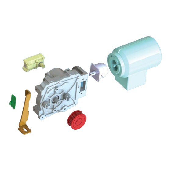
The Operating System The Operating System Components included NOTE: Connection cables for the power supply of the control system and a main switch possibly having to be installed, operating and safety elements form not part of the standard components. Operator with cable set to the control system ... -
Page 10: Main Components
The Operating System Main components Door operator with Wall bracket for idler pulley (optional) U-bracket Idler pulley with U-bracket Toothed belt Belt fixing device Supporting roller with U- bracket (optional) Wall bracket for door Belt fixing device for 2 operator (optional) door leaf (optional) Translated User Manual ... -
Page 11: Mode Of Operation And Functioning
Safety systems The operating system DICTAMAT Move meets the high safety demands of the EN 13241 standard, part 1 and its subordinated standards EN 12453 and EN ISO 13849-1. One of them being, that the sliding element stops after an extremely short distance when having recognized an obstacle. - Page 12 The Operating System Rating plate of the motor Rating plate with motor rating nominal speed rpm voltage type of protection serial number date of manufacture Rating plate with Rating plate of the system number operating system ...
-
Page 13: Safety
Safety Safety The personnel of the machine builder has to carefully and completely read and understand this user manual before they start to mount and put into operation the operating system. This user manual contains all important information necessary to prevent personal and material damage, to guarantee a trouble- free operation and not to affect the environment. -
Page 14: Intended Use
Safety Intended use The operating system has specially been designed for mounting on horizontally moved sliding elements (without incline) and may only be used for such applications. The weight and the dimensions must not exceed the values given by the customer. ... -
Page 15: Responsibilities Of The Machine Builder
Safety Responsibilities of the machine builder According to the Machinery Directive (2006/42/EG) the fitter who motorizes a sliding element is subject to the same responsibilities as the machine builder and therefore has to do the following: Issue the technical documentation which has to include the documents mentioned in the annex VII of the machinery directive. -
Page 16: Demands On The User Information For The Operator Of The Machine
Safety 3.4.2 Demands on the user information for the operator of the machine It is the machine builder’s responsibility to amend the information in this user manual according to the results of his risk assessment and the safety measures taken by him ... -
Page 17: Demands On The Qualification Of The Personnel
Safety Demands on the qualification of the personnel 3.5.1 Who may what? The operating system may only be built into the machine, connected and put into operation by instructed and qualified persons. Only a qualified electrical technician may work on the electrical system. If there is no such person available, a specialist firm has to be charged with the realization. -
Page 18: Personal Protective Equipment
Safety Personal protective equipment Always wear safety shoes according to EN ISO 20345, category S1 (A+FO+E) when working with or on the operating system: antistatic oil and petrol resistant sole energy absorption in the heel area steel caps. Always wear oil resistant work gloves according to EN 388 when performing tasks which require a hand protection. -
Page 19: Technical Data
Technical Data Technical Data Dimensions and weights Packed state Dimensions (length x width x 620 x 340 x 270 mm height) Control system + operator + accessories Weight max. approx. 30 kg Electrical system 230 VAC, 50 – 60 Hz Rated input voltage Power consumption max. -
Page 20: In-House Transport, Unpacking
In-House Transport, Unpacking In-House Transport, Unpacking Safety WARNING Squeezing hazard for hands and feet The door operator can topple over and/or fall down during transport. This can result in severe crushing injuries of hands and feet. There can be sharp edges on the operator and the accessories. -
Page 21: Mounting, Installation
Mounting, Installation Mounting, Installation Dimensions and fixing part no. 740000 or part no. 740005 part no. 740060 ׀ Translated User Manual MultiMove MultiControl page 21 drive system control system Version 2020-07... -
Page 22: Safety
Mounting, Installation Safety WARNING Severe injuries due to unexpected starting or failure of safety devices All safety functions of the complete installation have to be realized by the machine builder of the superior machine, see 3.4, Responsibilities of the machine builder. - Page 23 Mounting, Installation WARNING Risk of injury by falling parts Insufficient fixing of the operator and accessories can result in injuries. Observe the indicated tightening torques of the fixing screws. Sufficient stability of the fixing points Sufficient dimensioning of the fixing elements provided by the customer NOTE: Serious damage of machinery parts The control systems can fail due to external objects or inappropriate...
-
Page 24: Mounting Of The Operating System
Mounting, Installation Mounting of the operating system Determining the mounting positions of the operator and the accessories. When mounting take into consideration the standard length of 2 m of the connection cable between control system and operator. Wall mounting: Fix the wall bracket to the wall, oblong holes for max. M12 screws. - Page 25 Mounting, Installation Fix the U-bracket with the included M10 screws to the operator, tightening torque 49 Nm. Fix the U-bracket with the operator with the included M10 screws to the wall bracket. Align the operator. Tightening torque 49 Nm. ׀ Translated User Manual ...
- Page 26 Mounting, Installation Remove the cover of the driving wheel. Mounting of the idler pulley: Wall mounting: Fix the wall bracket to the wall, oblong holes for max. M10 screws. Take care of sufficient fixing (minimum 3 screws, see drawing of hole pattern).
- Page 27 Mounting, Installation Open and close the sliding element manually once and control whether the wheel hangers strike somewhere. Mounting of the belt fixing device Horizontal position: The device should be in an as central position as possible. Vertical position: The vertical position depends on whether the device shall be connected to the upper or lower part of the toothed belt/chain.
- Page 28 Mounting, Installation (10) Check the alignment of operator, idler pulley and belt/chain tensioner (the system components have to be in true alignment). If necessary, readjust them. Retighten all screws (for tightening torques see above). (11) Then loosen the M10 screw in the axis of the idler pulley, tension the toothed belt/chain with the lateral screw (wrench size 17) on the idler pulley.
-
Page 29: Troubleshooting
Troubleshooting Troubleshooting WARNING Severe injuries due to unexpected starting When working on the system when the control system is switched on, the driving system can start unexpectedly and an uncontrolled, dangerous behaviour of machine can happen. This includes the risk of squeezing or gripping by moving parts of the door drive or accessories. -
Page 30: Maintenance
Perform only maintenance work described in this chapter. In case of maintenance work which is not described in this chapter, always contact the DICTATOR customer service or a service center authorized by DICTATOR. WARNING... - Page 31 Maintenance WARNING Risk of injury due to stored energy Releasing the tension of the toothed belt in a wrong way may result in injuries by the tensioned toothed belt. Before starting to work on the toothed belt or the belt fixing device, release the tension of the belt at the idler pulley (see chapter Mounting of the operating system, 6.3 (11)).
-
Page 32: Inspection And Maintenance Plan
Maintenance Inspection and maintenance plan Installation an = as necessary, Err = in case of an error indication on the display, d = daily, m = monthly, ¼ = quarterly, an = annually Works to be performed ¼ Check the fixing points and the screws Check the toothed belt (wear, tension) Check the sliding element and the hardware for damage... -
Page 33: Checking Of Cables, Wires And Connections
Maintenance 8.2.1 Checking of cables, wires and connections (13) Switch off the driving system. See chapter Troubleshooting. (14) Check cables, wires and connections for: Correct and firm seat. If necessary: Adjust the seat of cables, wires and connections. Tensile load, load caused by objects. If necessary: Relieve the cables, wires and connections of the load. -
Page 34: Wear Parts, Spares
Spare and wear parts the change of which is not described in this manual may only be replaced by the DICTATOR service or a service center authorized by DICTATOR. For the driving system only original spare parts may be used. -
Page 35: Proper Disposal
Proper Disposal Proper Disposal Safety WARNING Dangerous electrical voltage Power packs store electrical energy in capacitors. Disconnect the machine from the mains supply. Secure the control system against accidental switching-on. Wait for at least 15 minutes after having switched off the machine until the energy stored in the capacitors has run down.
Need help?
Do you have a question about the DICTAMAT Move and is the answer not in the manual?
Questions and answers