Advertisement
Quick Links
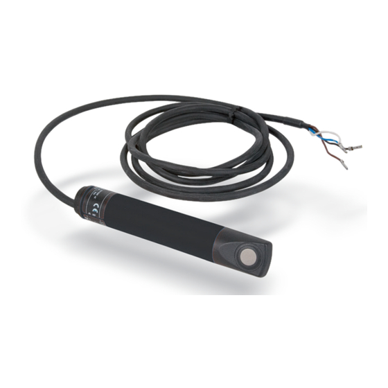
Airflow monitor SL 520 1.3A (analog output)
Product description / function
HVAC technology employs airflow monitors to monitor e.g.
electrical air heaters. The functionality of HVAC systems can
even be monitored when monitoring is not possible with elec-
tronic belt monitors, e.g. on direct-drive blowers. This is a cost-
effective alternative to pressure boxes or wind vane monitors.
The device operates based on calorimetric principles. The ana-
lysis electronics and the LEDs are integrated into the cylindrical,
smooth plastic housing. The airflow monitor records and con-
verts the flow velocity into an analog voltage signal. The sensor
is permanently calibrated by the factory and is not adjustable.
Technical Data
Power supply:
24 V DC ± 10 %, < 35 mA
Sensor range:
2 – 20 m/s
(output Ua = 1 – 10 V,
non-linear – see chart)
Fault thresholds:
± 0.7 m/s plus approx. ± 7 % of the
measured value
Medium temperature:
-10 – +50°C
Maximum rated
temperature gradient
of the medium:
1 K/min
Pressure rating:
1 bar
Visual function
display:
LED
Startup & operation:
green LED on
Ambient conditions:
-10 – +50 °C, max. 90 % relative
humidity
Startup time:
90 s (output = xx V)
Protection type:
IP 65
Electrical connection:
PUR cable 2 m, 4 x 0.5 mm
Output:
0 – 10 V analog
U a [V]
10
9
8
7
6
5
4
3
2
1
2
4
6
8
Dimensions:
142 x 23 mm Ø (L x D)
Probe depth:
min. 34 mm
max. 115 mm
Sensors PG1 | Data sheet No. 11102 | Version 08-2019 | 1 | 2
2
10
12
14
16
18
20
v [m/s]
Advertisement

Related Manuals for Oppermann Regelgeräte SL 520 1.3A


Summary of Contents for Oppermann Regelgeräte SL 520 1.3A
- Page 1 Airflow monitor SL 520 1.3A (analog output) Technical Data Power supply: 24 V DC ± 10 %, < 35 mA Sensor range: 2 – 20 m/s (output Ua = 1 – 10 V, non-linear – see chart) Fault thresholds: ± 0.7 m/s plus approx. ± 7 % of the...
- Page 2 Airflow monitor SL 520 1.3A Installation Electrical connection Please observe these instructions. All work (such as installation, Disconnect the system from power. Connect the sensor electrical connection, startup, operation, and maintenance) as indicated on the type tag. must only be performed by sufficiently qualified tradesmen. The respectively applicable local rules and regulations (e.g.
Need help?
Do you have a question about the SL 520 1.3A and is the answer not in the manual?
Questions and answers