Advertisement
Quick Links
Advertisement

Related Manuals for American Backflow Deringer 20

Summary of Contents for American Backflow Deringer 20
- Page 1 20, 20X, 20G, 20GX 2” – 8”...
-
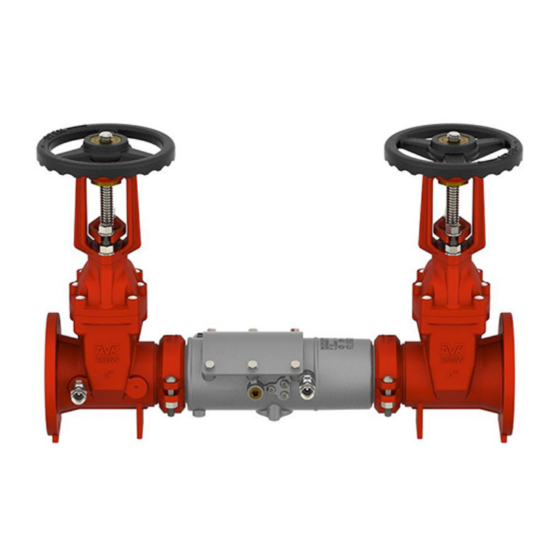
Page 2: Product Overview
Product Overview Production of the Model 20 (DCA) began in 2014. The “X” and “GX” series come in 4” and 6” sizes only. This indicates internal check valves that are larger than line size. For example 6” uses 8” parts. The “G”... - Page 3 Single Access Cover Removal The access cover is secured by bolts and o-ring sealed. There is no spring load on the cover. Remove bolts and tapered washers.
- Page 4 Check Valve Removal Modules are o-ring sealed and secured by retaining bolts located on the outside of the valve body. 2”- 4” sizes: Loosen the six 7/32” allen bolts until they are flush with the inner wall of the body. 6”- 8”...
- Page 5 Check Valve Removal Modules are o-ring sealed. Remove check 1 first, then check 2. Using a flat blade screwdriver, gently pry the module out of the body.
- Page 6 Check Disc Replacement Remove 4 tower screws on the front or back of the check module. The torsion spring is captured and does not need to be retained. Remove the tower from the check seat. Remove retaining screws from the disc retainer.
- Page 7 Check Seat Service The check seat is part of the module. If seat is damaged, the entire module will have to be replaced.
- Page 8 First Check Valve Reassembly Proper orientation of the tower and seat is critical for First check operation. Re-attach the tower to the seat with the spring arms and seat protrusions facing UP.
- Page 9 Second Check Valve Reassembly Proper orientation of the tower and seat is critical for Second check operation. Re-attach the tower to the seat with the spring arms facing DOWN and seat protrusions facing UP.
- Page 10 Second Check Installation Check 2 must be installed before check 1. Insert check 2 into body with tower pointing down stream. Push check into place until o-ring is fully seated. Do not tighten retaining screws until check 1 is installed.
- Page 11 First Check Installation Check 2 must be installed before check 1. Insert check 1 into body with tower pointing down stream. Push check into place until o-ring is fully seated.
- Page 12 Check Valve Reassembly Notes Once check 1 and check 2 are fully seated, tighten the 6 retaining bolts on the outside of the body. Make sure that the retaining bolts do not bind against the check valves.
- Page 13 Access Cover Reassembly Place the access cover on the main body. Make sure cover o-ring maintains the correct position. Insert cover bolts and tapered washers. Tapered washers are necessary for water tight seal. Tighten the cover bolts sequentially and by alternating from side to side.
Need help?
Do you have a question about the Deringer 20 and is the answer not in the manual?
Questions and answers