Advertisement
Quick Links
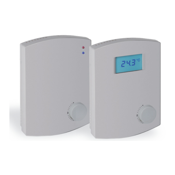
OPP-ROOM® Room Temperature Controller C1-...
Technical Data
Valid from Firmware V 2.14
Power supply:
24 V AC/DC -10% / +15%, max. 1 W
Outputs:
C1-TV
3 x 0 – 10 V DC < 5mA
C1-MOD / BAC
digital + 3 x 0 – 10 V DC
2 switching outputs
24 V AC (Triac),
2 A max.
Temperature sensor range: 0 – 50 °C
Accuracy ± 0.5 °C
Ambient conditions:
Operating temperature:
0 – 50 °C
Operating ambient humidity: 0 – 95% RH
(non-condensing)
Storage temperature:
-30 – 70 °C
Storage ambient humidity:
0 – 95% RH
(non-condensing)
Option L
LED blue and red
for displaying cooling and
heating mode
Option D
LCD display
for displaying
temperature, setpoint, and
controller state with
backlighting
(software-configurable)
Protection type:
IP 20
Housing:
ABS plastic, self-extinguishing,
white, similar to: RAL 9010
Wall installation
Dimensions:
(L x W x D) approx. 86 x 120 x 25 mm
Weight:
180g
Cable connection:
Screw terminals 0.05 – 1.5 mm²
•
New „Longline" design
- design-protected
•
Large LCD display with backlight
•
Setpoint potentiometer with individually
adjustable midpoint and min/max limits
•
Analog outputs voltage (0 – 10 V DC)
•
Convenient parameter programming with
OR-C configuration Software
•
Also available as BACnet / Modbus
Function
For controlling interior air temperatures.
Installation
All work (such as installation, electrical connection, startup,
operation, and maintenance) must only be performed by suf-
ficiently qualified tradesmen. The respectively applicable local
rules and regulations (e.g. national building codes, electrical/
VDE regulations, etc.) must be observed. Installers and opera-
ting entities are required to sufficiently familiarize themselves
before startup. Read the product description before operating
the equipment. Verify that the product can be used for the
relevant application without restrictions. We are not liable for
printing errors and changes after printing. Appropriate use
implies compliance with operating and installation instructions.
We are not liable for losses due to inappropriate use. Unautho-
rized or inappropriate manipulations or modifications of the
device render the operating permit, the product warranty and
warranty claims null and void.
Temperature and humidity sensors | Data sheet No. 20530 | Version 10-2020 | 1 | 12
Advertisement

Subscribe to Our Youtube Channel
Related Manuals for Oppermann Regelgeräte OPP-ROOM C1 Series

Summary of Contents for Oppermann Regelgeräte OPP-ROOM C1 Series
- Page 1 OPP-ROOM® Room Temperature Controller C1-… • New „Longline“ design - design-protected • Large LCD display with backlight • Setpoint potentiometer with individually adjustable midpoint and min/max limits • Analog outputs voltage (0 – 10 V DC) • Convenient parameter programming with OR-C configuration Software •...
-
Page 2: Electrical Connection
Room Temperature Controller C1-… Electrical Connection Voltage transmitter C1-TV-R... 24 VAC Digital output 1 Digital output 2 24 VAC 24 VAC/DC 24 VAC/DC DO1 + DO2 Voltage output with Triac, Supply requires 24 V AC power supply. Output 0 – 10 V DC Power supply 24 V AC/DC Configuration Output 0 –... -
Page 3: Accessories (Ordered Separately)
Room Temperature Controller C1-… Accessories (ordered separately): Description Type Windows configuration software OR-C CAB-02 1.8 m USB cable For all following pages, please also note the instructions in specification sheet 20560 (OR-C configuration software)! LCD display (types C1-..-R-D-P1) Controllers of type C1-..-R-D-P1 have on on-board LCD used to display the current controller status. The display is also used to show the configuration settings. - Page 4 Room Temperature Controller C1-… Configuration parameters and programming Parameters can be adjusted with the help of the sensor configuration software. A USB cable is used to connect the PC with previously installed OR-C to the program- Programming interface ming head of the sensor, as shown in the figure on the right. USB-Cable CAB-02 The correct procedure for connecting the sensor via USB is as follows: •...
- Page 5 Room Temperature Controller C1-… PARAMETER CONFIGURATION DISPLAY SELECTION ANALOG OUTPUT 3 (AO3) PARAM 1: PARAM 11: PARAM 21: 0 - Bus SELECTION / DIGITAL INPUT ADJUSTMENTS 1 - Off 0 - Night mode = SETPOINT CENTER 2 - Heating level 1 everything off (default) (RANGE –...
- Page 6 Room Temperature Controller C1-… HEATING LEVEL 2 HEATING LEVEL 1 COOLING LEVEL 1 COOLING LEVEL 2 100% CNTSP MEASURED TEMPERATURE DZ = Deadzone (default: 1.5K) CNTSP = SETPOINT CENTER (default: 21°C) NOTES: • The number of heating and cooling levels can be set to 0, 1, or 2. •...
- Page 7 Room Temperature Controller C1-… Digital outputs - operating modes and wiring examples The digital outputs (24 V AC Triacs, 2 A max.) can be configured as outputs for a 3-point control, as PWM control (pulse width modulation) or simple on/off switches (2-point control). The type of control is selected with a configuration parameter. When 3-point control is selected, the controller will open, e.g.
- Page 8 Room Temperature Controller C1-… 24 V Change-Over Coil: In this example THY1 is a Digital output 1 thermal drive for a valve. THY1 has a 24 V power Digital output 2 supply, and its position is determined via an 24 V AC/DC analog signal 0 - 10 V.
- Page 9 Room Temperature Controller C1-… Underfloor high/low limit control (HSP/LSP) Room temperature is controlled by modulating valve controlling the water supply to the underfloor heating. The C1-controller modulates the valve according to the setpoint (SP) set by the user. The speed of the response is controlled by the PI control set- tings.
-
Page 10: Modbus Register
Room Temperature Controller C1-… Adjusting the Modbus address and the baud rate The Modbus address and the baud rate can be programmed either with the OR-C configuration tool together with the CAB-02 data cable or directly on the unit with the bit switches. PROGRAMMING THE BAUD RATE PROGRAMMING THE TRANSMITTER BUS ADDRESS BAUD RATE... - Page 11 Room Temperature Controller C1-… Register Parameter description Data type Raw data Range FUNCTION CODE 04 - READ INPUT REGISTER 30000 Temperature, on- board sensor Signed 16 -400 – 3.020 -40.0 – 150.0 °C (-40.0 – 302.0 °F) 30001 Temperature, external sensor on Signed 16 -400 –...
- Page 12 Room Temperature Controller C1-… Register Parameter description Data type Raw data Range 40014 Analog output Y1, mode Unsigned 16 0 – 6 0 = Value via data bus 1 = Off 2 = Heating level 1 (Default) 3 = Heating level 2 4 = Cooling level 1 5 = Cooling level 2 6 = Air-side control...
- Page 13 Room Temperature Controller C1-… Register Parameter description Data type Raw data Range 40100 forced reset/warm boot Unsigned 16 0 – 1 0 = Normal 1 = Forced reset 40101 update non-volatile memory Unsigned 16 0 – 1 0 = Normal see note 3 1 = Update Note 1: The Modbus address can only be configured by the OR-C tool when bit switches 1 –...
Need help?
Do you have a question about the OPP-ROOM C1 Series and is the answer not in the manual?
Questions and answers