Advertisement
Quick Links
SERVICE MANUAL
DUMPER
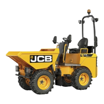
1THT
EN - 9813/5200 - ISSUE 2 - 07/2018
This manual contains original instructions, verified by
the manufacturer (or their authorized representative).
Copyright 2017 © JCB SERVICE
All rights reserved. No part of this publication may
be reproduced, stored in a retrieval system, or
transmitted in any form or by any other means,
electronic, mechanical, photocopying or otherwise,
without prior permission from JCB SERVICE.
www.jcb.com
Foreword
The Operator's Manual
You and others can be killed or seriously injured
if you operate or maintain the machine without
first studying the Operator's Manual. You must
understand and follow the instructions in the
Operator's Manual. If you do not understand
anything, ask your employer or JCB dealer to
explain it.
Do not operate the machine without an Operator's
Manual, or if there is anything on the machine you
do not understand.
Treat the Operator's Manual as part of the machine.
Keep it clean and in good condition. Replace the
Operator's Manual immediately if it is lost, damaged
or becomes unreadable.
Contents
01 - Machine
06 - Body and Framework
09 - Operator Station
15 - Engine
18 - Fuel and Exhaust System
21 - Cooling System
24 - Brake System
25 - Steering System
27 - Driveline
30 - Hydraulic System
33 - Electrical System
72 - Fasteners and Fixings
75 - Consumable Products
78 - After Sales
Advertisement

Summary of Contents for jcb 1THT
- Page 1 Operator's Manual. You must understand and follow the instructions in the Operator's Manual. If you do not understand anything, ask your employer or JCB dealer to explain it. SERVICE MANUAL Do not operate the machine without an Operator's Manual, or if there is anything on the machine you do not understand.
- Page 2 15 - Engine 24 - Air Filter 03 - Outer Element 03 - Outer Element Clean Clean ............. 15-58 1. Make the machine safe. Remove and Install ........15-59 2. Get access to the air filter. 3. Clean the area around the air cleaner. 4.
-
Page 3: Remove And Install
15 - Engine 24 - Air Filter 03 - Outer Element Remove and Install Install 1. The installation procedure is the opposite of the removal procedure. Remove 1. Make the machine safe. Refer to (PIL 01-03). 2. Isolate the battery. Refer to (PIL 33-03). 3. - Page 4 15 - Engine 54 - Flywheel 54 - Flywheel Contents Page No. 15-54-00 General ........................... 15-85 15-54-12 Drive Plate ........................15-86 15 - 84 9813/5200-2 15 - 84...
- Page 5 15 - Engine 54 - Flywheel 00 - General 00 - General Introduction Flywheels are used to provide continuous energy in systems, where the energy source is not continuous. In such cases, the flywheel stores energy when torque is applied by the energy source, and it releases stored energy when the energy source is not applying torque to it.
- Page 6 15 - Engine 54 - Flywheel 12 - Drive Plate 12 - Drive Plate Install 1. The installation procedure is the opposite of the Remove and Install removal procedure. Additionally do the following step. Remove 2. Tighten the bolts to the correct torque value. 1.
- Page 7 15 - Engine 75 - Starter Motor 00 - General 00 - General Introduction Introduction ..........15-101 The electric starter motor is either a permanent- Health and Safety ........15-102 magnet or a series-parallel wound direct current electric motor with a starter solenoid mounted on to Component Identification ......
-
Page 8: Health And Safety
15 - Engine 75 - Starter Motor 00 - General Health and Safety WARNING Make the machine safe before working on it. Park the machine on level ground and lower the loader arm. Stop the engine and remove the ignition key. Make sure the park brake is engaged. -
Page 9: Component Identification
15 - Engine 75 - Starter Motor 00 - General Component Identification Figure 107. 1 Solenoid 2 Brush gear 3 Tie bolts Figure 108. A Solenoid positive terminal (From battery) B Solenoid terminal (From ignition switch) C Negative terminal (To ground) D Solenoid positive after contact terminal (To motor) 15 - 103... -
Page 10: Check (Condition)
15 - Engine 75 - Starter Motor 00 - General Check (Condition) Figure 110. Before carrying out the multimeter tests, check the battery condition and make sure that all the applicable electrical connections are clean and tight. Make sure that the starter motor fixing bolts are tightened to the correct torque. - Page 11 15 - Engine 75 - Starter Motor 00 - General Figure 112. 5.1. If the reading is above the maximum permissible voltage, a high resistance in the earth lead or connections is indicated. 6. Connect the voltmeter between battery positive and the starter main terminal.
- Page 12 15 - Engine 75 - Starter Motor 00 - General Remove and Install Figure 118. Remove 1. Make the machine safe. Refer to: PIL 01-03-27. 2. Isolate the battery. Refer to: PIL 33-03. 3. Remove the floor plate. Refer to: PIL 09-78-00. Battery positive cable 4.
- Page 13 15 - Engine 75 - Starter Motor 00 - General Figure 121. C Electrical connector 11. Remove the starter motor. Figure 122. D Starter motor Install 1. The installation procedure is the opposite of the removal procedure. Additionally do the following step.
- Page 14 15 - Engine 75 - Starter Motor 06 - Brush Gear 06 - Brush Gear Remove and Install The starter motor brushes are an integral part of the starter motor. This part is a non-serviceable part if it fails, replace the complete starter motor.
- Page 15 Our support email: ebooklibonline@outlook.com...


Need help?
Do you have a question about the 1THT and is the answer not in the manual?
Questions and answers