
Related Manuals for Miller Deltaship 502


Summary of Contents for Miller Deltaship 502
- Page 1 OM-227 512C 2006−12 Processes MIG (GMAW) Welding Flux Cored (FCAW) Welding Description Arc Welding Power Source Deltaship 502 File: MIG (GMAW) Visit our website at www.MillerWelds.com...
-
Page 2: Table Of Contents
TABLE OF CONTENTS SECTION 1 − SAFETY PRECAUTIONS - READ BEFORE USING ........1-1. -
Page 3: Section 1 − Safety Precautions - Read Before Using
SECTION 1 − SAFETY PRECAUTIONS - READ BEFORE USING som _3/05 Y Warning: Protect yourself and others from injury — read and follow these precautions. 1-1. Symbol Usage Means Warning! Watch Out! There are possible hazards with this procedure! The possible hazards are shown in the adjoining symbols. - Page 4 ARC RAYS can burn eyes and skin. BUILDUP OF GAS can injure or kill. D Shut off shielding gas supply when not in use. Arc rays from the welding process produce intense visible and invisible (ultraviolet and infrared) rays D Always ventilate confined spaces or use that can burn eyes and skin.
-
Page 5: Additional Symbols For Installation, Operation, And Maintenance
D Read Owner’s Manual before using or servic- support unit. ing unit. D If using lift forks to move unit, be sure forks are D Use only genuine Miller/Hobart replacement long enough to extend beyond opposite side of parts. unit. -
Page 6: Principal Safety Standards
1-5. Principal Safety Standards Safety in Welding, Cutting, and Allied Processes, ANSI Standard Z49.1, Boulevard, Rexdale, Ontario, Canada (phone: from Global Engineering Documents (phone: 1-877-413-5184, website: 800−463−6727 or in Toronto 416−747−4044, website: www.csa−in- www.global.ihs.com). ternational.org). Practice For Occupational And Educational Eye And Face Protection, Recommended Safe Practices for the Preparation for Welding and Cut- ANSI Standard Z87.1, from American National Standards Institute, 11 ting of Containers and Piping, American Welding Society Standard... -
Page 7: Section 2 − Definitions
SECTION 2 − DEFINITIONS 2-1. General Precautionary Label Warning! Watch Out! There are possible hazards as shown by the symbols. Electric shock from welding electrode or wiring can kill. 1.1 Wear dry insulating gloves. Do not touch electrode with bare hand. Do not wear wet or damaged gloves. -
Page 8: Input Connection Label
2-2. Input Connection Label Warning! Watch Out! There 1/96 are possible hazards as shown by the symbols. Electric shock from wiring can kill. Disconnect input plug or power before working on machine. Read the Owner’s Manual before working on this machine. -
Page 9: Section 3 − Installation
SECTION 3 − INSTALLATION 3-1. Specifications Amperes Input at Rated Load Output, 50 Hz, Three-Phase Rated Welding Rated Welding Voltage Range Voltage Range Output 380 V Max OCV DC 387 A @ 38 Volts DC, 100 % Duty Cycle 48.9 25.1 10 −... -
Page 10: Volt-Ampere Curves
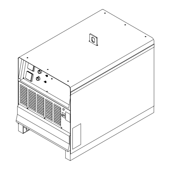
3-3. Volt-Ampere Curves Volt-ampere curves show minimum and maximum voltage and amperage output capabilities of unit. Curves of other settings fall between curves shown. DC AMPERES Tech Pub 3-4. Selecting A Location Lifting Eye Lifting Forks Use lifting eye or lifting forks to move unit. -
Page 11: Dimensions And Weights
3-5. Dimensions And Weights Dimensions Dimensions 30 in (762 mm) Including lift eye 23 in (584 mm) 30-1/2 in (775 mm) Including strain relief 27-1/2 in (699 mm) 3/4 in (19 mm) 4 Holes 4 Holes 21-1/8 in (537 mm) 1-1/8 in (29 mm) 7/16 in (11 mm) Dia Weight... -
Page 12: Ac Receptacles And Power Source Circuit Breakers
3-7. AC Receptacles And Power Source Circuit Breakers Y Turn power before connecting to receptacle. 115 V 15 A AC Receptacle 36 V 15 A AC Receptacle RC10 (For CO Heater) Circuit Breaker CB1 Circuit Breaker CB2 Circuit Breaker CB3 CB1 protects 115 volt ac receptacle RC9 from overload. -
Page 13: Connecting To Weld Output Terminals
3-9. Connecting To Weld Output Terminals Do not place anything between weld cable terminal and copper bar. Tools Needed: 3/4 in (19 mm) 803 778-A Correct Installation Incorrect Installation Y Turn off power before connecting to Weld Output Terminal minal. Slide weld cable terminal onto weld weld output terminals. -
Page 14: Changing Inductance
3-10. Changing Inductance Y Turn power before changing stabilizer taps. Remove cover. Stabilizer Z Lead 25 Stabilizer Z1 Center Tap Stabilizer Z1 Ending Lead 26 Tapped stabilizer Z is factory connected to the stabilizer center tap which is recommended for use with most gas-shielded and self- shielded flux cored wires. -
Page 15: Remote 6-Socket Receptacle Rc8 Information
3-11. Remote 6-Socket Receptacle RC8 Information Socket Socket Information Motor voltage; 0 to +21 volts dc with motor M1 running. Gas valve voltage; +24 volts dc when gun is triggered or when purging gas. Trigger/Jog; Normally +15 volts dc; 0 volts dc when gun is triggered and + 7 volts dc when Jog switch PB1 is pressed. -
Page 16: Connecting Input Power
3-13. Connecting Input Power = GND/PE Earth Ground 3/8, 1/2 in 804 429 Y Installation must meet all National Welding Power Source Input Power Disconnect Device Input Power Con- and Local Codes − have only quali- Connections nections fied persons make this installation. Strain Relief Disconnect Device (switch shown in OFF position) -
Page 17: Section 4 − Operation
SECTION 4 − OPERATION 4-1. Controls A. Welding Power Source 227 494 Analog Meters to purge gas lines, or to adjust gas regulator. settings from weld controls on wire feeder pendant. At second trigger closure, welding Voltmeter and ammeter display actual output Mode Switch arc stops. - Page 18 B. Wire Feeder Pendant Controls are pendant mounted. An optional remote pendant extension cord is available. Voltage Control Use control to set welding power source voltage at the wire feeder. Numbers are for reference only. Amperage Control Use control to adjust amperage from min.
-
Page 19: Section 5 − Maintenance & Troubleshooting
SECTION 5 − MAINTENANCE & TROUBLESHOOTING 5-1. Routine Maintenance Y Disconnect power before maintaining. 3 Months Clean Repair or Replace tighten weld replace unreadable terminals. cracked labels. weld cable. 6 Months Blow out or vacuum inside. During heavy service, clean monthly 5-2. - Page 20 Trouble Remedy Wire does not feed, feeder completely Check 6−pin plug PLG8 connections (see Section 3-11). inoperative. Check input power. Wire does not feed. Check circuit breaker CB2 on welding power source, and reset if necessary (see Section 3-7). Check gun trigger connection at wire feeder (see wire feeder owner’s manual). Check gun trigger leads and trigger switch.
-
Page 21: Section 6 − Electrical Diagram
SECTION 6 − ELECTRICAL DIAGRAM 227 504-C Figure 6-1. Circuit Diagram OM-227 512 Page 19... -
Page 22: Section 7 − Parts List
SECTION 7 − PARTS LIST Hardware is common and not available unless listed. Figure 7-1. Main Assembly 804 480 OM-227 512 Page 20... - Page 23 Item Dia. Part Mkgs. Description Quantity Figure 7-1. Main Assembly ....+179 430 ..Panel, Side ...........
- Page 24 Item Dia. Part Mkgs. Description Quantity Figure 7-2. Panel, Rear w/Components (Figure 7-1 Item 12) ....173 283 ..Chamber, Plenum 14 In .
- Page 25 ..Nameplate, Miller Deltaship ........
- Page 26 Item Dia. Part Mkgs. Description Quantity Figure 7-3. Panel, Front w/Components (Figure 7-1 Item 23) (Continued) ....159 036 ..Lens, Led Clear Panel Mtg .
- Page 27 Effective January 1, 2006 (Equipment with a serial number preface of “LG” or newer) This limited warranty supersedes all previous Miller warranties and is exclusive with no other Warranty Questions? guarantees or warranties expressed or implied. LIMITED WARRANTY − Subject to the terms and conditions...
- Page 28 Appleton, WI 54914 USA International Headquarters−USA USA Phone: 920-735-4505 Auto-Attended USA & Canada FAX: 920-735-4134 International FAX: 920-735-4125 European Headquarters − United Kingdom Phone: 44 (0) 1204-593493 FAX: 44 (0) 1204-598066 © PRINTED IN USA 2006 Miller Electric Mfg. Co.
Need help?
Do you have a question about the Deltaship 502 and is the answer not in the manual?
Questions and answers