
Related Manuals for A-TS TECHNOLOGY Pulse Series

Summary of Contents for A-TS TECHNOLOGY Pulse Series
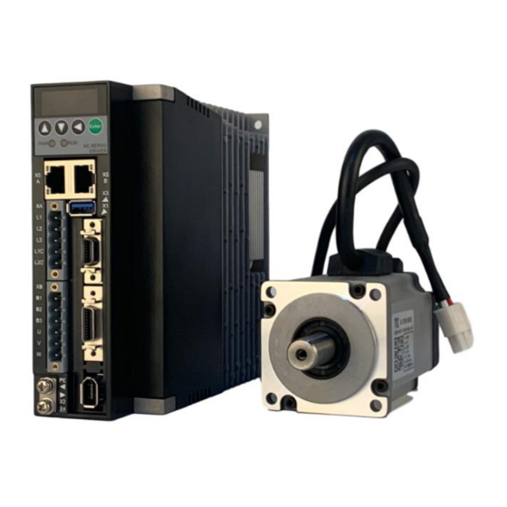
- Page 1 RT10 Pulse Series AC Servo Drive User Manual A-TS TECHNOLOGY CORPORATION LIMITED www.a-ts.cn...
- Page 2 A-TS Technology RT10 DECLARATION Without written permission, reprint or copy is strictly forbidden. Unauthorized copying, dissemination or use of this document and its contents is prohibited. Violators will be liable for compensation. All rights, including the rights granted by patent rights and the registration rights of application models or designs will be reserved.
-
Page 3: Forward
A-TS Technology RT10 Forward The RT10 series ac servo is provided by A-TS Technology Co., Ltd. in China. To have a thorough understanding, please read this manual carefully and follow all safety precautions before moving, installing, operating and maintaining the servo. - Page 4 A-TS Technology RT10 In this document, the following symbols may appear. The meaning they represent is as follows. Symbol Instructions Attention, please! If there is improper operation, it may cause serious consequences such as personal safety, equipment safety or environmental safety.
-
Page 5: Table Of Contents
A-TS Technology RT10 Contents Forward ..................3 Contents ..................5 1 Product Information ..............8 1.1 Product introduction .............. 8 1.2 Naming rule ................8 1.3 Technical specifications ............9 1.4 Adapted motor ..............12 2 Installation and Wiring ............... 13 2.1 Installation ................ - Page 6 A-TS Technology RT10 2.2.5 USB debugging port X3 definition ......... 25 2.2.6 RS485 communication port X5A/X5B definition .... 26 2.2.7 Wiring of three control mode ......... 27 3 Display and Keyboard Operation ..........30 3.1 Basic operation ..............30 3.2 Menu level one ..............
- Page 7 A-TS Technology RT10 4.4 Speed control ..............43 4.5 Inertia identification ............. 44 4.6 Automatic gain adjustment ..........45 5 Parameters ................47 5.1 Parameter list ..............47 5.1.1 PA parameters.............. 47 5.1.2 Fn parameters .............. 57 6 Fault Alarm ................64 6.1 Alarm code list ..............
-
Page 8: Product Information
A-TS Technology RT10 1 Product Information 1.1 Product introduction RT10 series servo is all digital ac servo drive, with high reliability, performance and cost effectiveness. Low voltage servo, working at single phase/three phase 220V AC, with low voltage motor ... -
Page 9: Technical Specifications
A-TS Technology RT10 ● Support this feature. × Don’t support this feature. 1.3 Technical specifications Table 1-1 RT10 series pulse series technical specification Model RT10 series ac servo drive □□□ RT10-PA L-E02 Single/three-phase Three-phase Power supply AC220V, -15% - +10%,... - Page 10 A-TS Technology RT10 ABZ incremental encoder, Standard Feedback incremental encoder, and Absolute encoder Control mode Position / Speed / Torque Up to 11 input terminals (optoelectronic isolation). Servo-enable, alarm clearance, CWL, CCWL, forward torque limitation, reverse torque limitation, zero speed clamp, internal speed...
- Page 11 A-TS Technology RT10 input ≤ 500kpps, single-ended input ≤ 200kpps frequency High speed pulse command port, differential input≤4Mpps Direction + pulse sequence. CW+CCW pulse sequence. Command mode Two phase A/B orthogonal pulse Internal position command Numerator, 1 - 32767...
-
Page 12: Adapted Motor
A-TS Technology RT10 command pulse frequency, etc. Over speed, over voltage, over current, over Protection function load, abnormal braking, abnormal encoder, position exceeding tolerance, etc. Speed ≥1500Hz frequency response Features Speed ≤±0.03% (Load 0 - 100%) fluctuation ≤±0.02% (Power -15% - +10%) -
Page 13: Installation And Wiring
A-TS Technology RT10 2 Installation and Wiring 2.1 Installation When installing, operating and maintaining the RT series ac servo drive, please follow the instructions in the manual. 2.1.1 Installation environment Working temperature, 0 - 45℃ Working humidity, below 80% RH (no condensation) ... -
Page 14: Products Appearance And Dimensions
A-TS Technology RT10 2.1.2 Products appearance and dimensions □□ Figure 2-1 RT10- 005L Product appearance and dimensions (Unit, mm) Figure 2-2 RT10-□□010L Product appearance and dimensions (Unit, mm) - Page 15 A-TS Technology RT10 Figure 2-3 RT10-□□015L Product appearance and dimensions (Unit, mm) Figure 2-4 RT10-□□020L/RT10-□□030L Product appearance and dimensions (Unit,...
- Page 16 A-TS Technology RT10 Figure 2-5 RT10-□□050L Product appearance and dimensions (Unit, mm)
-
Page 17: Wiring And Terminals
B1 and B2. Figure 2-6 RT10-PA/RT10-PB pulse series AC servo drive wiring diagram RT-STP is the Servo Tuning Program. It’s a tuning software provided by the A-TS Technology. For more details, please contact with us at www.a-ts.cn. -
Page 18: Strong Power Terminals
A-TS Technology RT10 2.2.2 Strong power terminals Table 2-1 RT10 series drive strong power terminals Terminal Name Specifications labels Control power Connect to single phase 220V AC power. input terminals Connect to single / 3 phase 220V AC Main power power. -
Page 19: Command Terminal X1
A-TS Technology RT10 correspondingly. (Note, PE is the terminal for the metal heat sink on the drive) Only when the drive is connected to single phase ac power, L1C&L1 and L2C&L2 shall be shorted. So far, the 380V ac power shall not be used, or it will burn the drive out. - Page 20 A-TS Technology RT10 confirm the pin sequence according to the solder side as the figure above. Table 2-2 Command Terminal X1 Definition Signal name Pin No. Signal interpretation The digital input optocoupler common end. According to the digital input low level or...
- Page 21 A-TS Technology RT10 DI10 Digital input 10 DI11 Digital input 11 DO1+(S-RDY+) Digital output 1. The default function, servo ready output DO1-(S-RDY-) DO2+(ALM+) Digital output 2. The default function, servo alarm output DO2-(ALM-) DO3+ Digital output 3. The default function,...
- Page 22 A-TS Technology RT10 SIGN+. PULS+ Low-speed command pulse sequence input PULS- SIGN+ Low-speed command pulse direction input SIGN- PULSH+ High-speed command pulse sequence input PULSH- SIGNH+ High-speed command pulse direction input SIGNH- AI1+ Analog command channel 1 input AI1-...
-
Page 23: Encoder Terminal X2 Definition
A-TS Technology RT10 Encoder frequency division output, Phase Z, open collector output Reference level, signal ground Reference level, signal ground Shielding Shielding / protection of the ground ground 2.2.4 Encoder terminal X2 definition The servo motor encoder signal is input by the X2 terminal. The schematic diagram of encoder terminal pins is below. - Page 24 A-TS Technology RT10 EC-GND Encoder power / signal ground, 0V Encoder phase A signal input Encoder phase B signal input Encoder phase Z signal input Encoder phase U signal input Encoder phase V signal input Encoder phase W signal input...
-
Page 25: Usb Debugging Port X3 Definition
A-TS Technology RT10 CLK- Serial clock (When it is the Nikon/ Biss / Endat encoder) CLK+ Shield ground, it is connected to the metal shield layer of shield wire. 2.2.5 USB debugging port X3 definition This terminal is the USB3.0A plug, compatible with USB2.0. But it’s different from the standard USB3.0 definition. -
Page 26: Rs485 Communication Port X5A/X5B Definition
A-TS Technology RT10 USB_D+ USB data+ DGND USB signal / power ground RS232-TX RS232 send RS232-RX RS232 receive DGND RS232 signal ground D5V/D3V3 RS232 positive pole (optional) None Housing/ Floating shield ground Shell Do not connect USB3.0 cable to the drive directly, or it may cause damage to the drive or PC port. -
Page 27: Wiring Of Three Control Mode
A-TS Technology RT10 CAN bus data negative, CAN- reserved RS485+ RS485 Data+ DGND Reference ground DGND Reference ground RS485- RS485 Data- The RT10-PB series drive doesn’t support this function. 2.2.7 Wiring of three control mode The position control mode wiring sample graph... - Page 28 A-TS Technology RT10 RT10 servo Servo Motor drive Three- phase AC 220V Note:single-phase AC 220V connect to L1、L2 terminals DI-COM 3.3kΩ Servo enable DI1(SRV-ON) Alarm DO1+(SRDY+) D2(A-CLR) clearance Servo ready to output DO1-(SRDY-) CW drive prohibit DI3(POT) DO2+(ALM+) Servo alarm output DO2-(ALM-)...
- Page 29 A-TS Technology RT10 Servo motor RT10 servo drive Three-phase AC 220V Note: single-phase AC 220V connected to L1, L2 terminals DO1+(SRDY+) Analog command Servo ready to output DO1-(SRDY-) channel input 2 AGND DO2+(ALM+) Servo alarm output DO2-(ALM-) DO3+(POS+) Position reached output...
-
Page 30: Display And Keyboard Operation
A-TS Technology RT10 3 Display and Keyboard Operation 3.1 Basic operation The operator panel adopts five LED tubes, two LED indicators, and four keys, as shown in the Figure 4-1. Figure 3-1 operation panel Five Led tubes LED works to display the states and parameters of the servo drive. -
Page 31: Menu Level One
A-TS Technology RT10 Page down, to display page, decrease serial number or value. Return key, Return or cancel. Enter key, Enter or OK. Two LED indicator PWR, it indicates that the drive main circuit is powered on. RUN, it indicates that the drive has already been enabled, and the motor is powered on. -
Page 32: Menu Level Two
A-TS Technology RT10 Menu level two Menu level one Monitoring Parameter setting Auxiliary function Auxiliary parameters Parameter management Motor parameter Motor running Figure 3-2 Menu level one 3.3 Menu level two Enter the menu level two by selecting the different menu level one. - Page 33 A-TS Technology RT10 Motor speed r/min Motor speed 1000 r/min Current position pulse Current position 1202345 Current position high eight-bit (×100000 Pulse) System position System position command command 345 pulse Servo internal position Servo internal position command pulse command pulse -17345...
-
Page 34: Parameter Setting (Pa/Fn Parameter)
A-TS Technology RT10 3.3.2 Parameter setting (Pa/Fn parameter) In the menu level one, select and press the Enter to go to the parameter setting mode. Use the Page up or Page down key to select the parameter number, and press the Enter key to display the parameter value. Then use the Page up or Page down key to modify the parameter value. -
Page 35: Parameter Management
A-TS Technology RT10 In the RT10 series servo, the PA menu only displays parameters up to parameter 99 by default. If it is old version, change the PA0 to 527, it will display all the parameters. 3.3.3 Parameter management Parameter management mainly handles the operation between the parameter table and EEPROM. - Page 36 A-TS Technology RT10 It resets the MCU processor in the servo drive. It is equal to the drive does power cycle. After save the parameter, we could use this operation to avoid power the drive off and power it on again.
-
Page 37: Running
A-TS Technology RT10 4 Running 4.1 Set motor type Power on After the power is up, the PWR indicator is lit. If an alarm occurs, please check the wiring. Check the motor type Check the parameter PA1 value, and find the motor type corresponding to this parameter in the Motor selection guide. - Page 38 A-TS Technology RT10 matching the motor, it is the user-defined motor. Just change parameter PA1 to Save the modified parameters in Select in the menu level two, and press the Enter key. Keep pressing the Enter key for more than 3 seconds, and it will...
-
Page 39: Jog Trial Running
A-TS Technology RT10 digit (x10000) Z-pulse offset pulse 0 - 50000 (incremental) Motor pole pairs 1 - 60 Rated current 0.1 - 100.0(A) Rated torque 0.1 - 100.0(Nm) Rated speed 1 - 9000(rpm) Maximum speed 1 - 9000(rpm) Rotary inertia 0.0 - 200.00(x10... -
Page 40: Position Control
A-TS Technology RT10 4.3 Position control Position control is applied in the systems require precise positioning, such as CNC machine tools, textile machinery etc. The pulse command of the control system is the position command source. The pulse inputs by the PULS +/- and SIGN +/- input terminals. - Page 41 A-TS Technology RT10 Table 4-2 Parameters related to position command Factory Parameter Parameter Name Set value value description Control mode Position control Electronic gear Appropriate Electronic gear PA12 numerator value numerator Electronic gear Appropriate Electronic gear PA13 denominator value...
-
Page 42: Electronic Gear Setting
A-TS Technology RT10 Command pulse transmission path PA12 PULS Direction Input pulse Input pin Pulse command f1 SIGN filtering mode PA52 Position PA15 command f2 Position Pulse command f3 PA19/PA24 Smooth mode filtering PA14 PA13 Electronic gear Pulse + direction... -
Page 43: Speed Control
A-TS Technology RT10 4.4 Speed control Speed control is applied where precise speed control is required. It’s can also be configured by the upper device. Torque feed forward Motor Input speed Speed Speed Speed command Speed Speed loop Current... -
Page 44: Inertia Identification
A-TS Technology RT10 Time to decelerate DEC time Appropriate PA41 from maximum speed constant value to zero speed (ms) Speed command Appropriate Speed command PA36 filter time constant value smoothing time (ms) Analog AI1 filter Appropriate Analog smoothing Fn50... -
Page 45: Automatic Gain Adjustment
A-TS Technology RT10 ② Servo drive with the motor can work normally. ③ The motor and the load has been connected. The inertia identification process is as below. Set PA53 Set Fn69 Check the Input this value Dp20-Jr Value... - Page 46 A-TS Technology RT10 Low rigidity applications such as Grade 8 to 15 belts High rigidity applications such as ball Grade 15 to 20 screws and ball linear. Before using the automatic gain adjustment function, make sure to acquire the load inertia ratio correctly.
-
Page 47: Parameters
A-TS Technology RT10 5 Parameters 5.1 Parameter list The applicability column shows the applicable control mode. P means position control applicable, S means speed control applicable, T means torque control applicable, and ALL means it is applicable for position, speed and torque control all. - Page 48 A-TS Technology RT10 Control method 0 - 16 ★ Speed proportional 2 - 2000 150* gain Speed integral time 1.0 - 50.0* P, S constant 1000.0 Torque filter time 0 - 20.0 0.20 constant Speed feedback filter 0 - 10.00 0.50...
- Page 49 A-TS Technology RT10 3, bus instruction 4, internal location Bit0, Position command reverse direction Bit1, Speed command 00000b - PA15 Command reverse reverse 00000b ★ direction setting 11111b direction Bit2, Torque command reverse direction Bit3/4, rsv Location complete PA16...
- Page 50 A-TS Technology RT10 automatic identification Bit3:rsv Position command PA19 microsecond pulse signal filter time 0.0 - 20.0 ★ (us) constant Bit1, Control mode switch allowed PA20 Servo control 00000b - 00000b Bit2, IO jog ★ auxiliary switch 11111b function...
- Page 51 A-TS Technology RT10 Internal speed -9000 - PA27 command 1 9000 PA28 Arrival speed 0 - 3000 P, S Load rotation inertia PA29 0 - 8000 P, S ratio PA30 Motor torque overload 10 - 300 ★ alarm value...
- Page 52 A-TS Technology RT10 ms, max Deceleration time PA41 0 - 10000 speed to 0 constant time Incremental encoder PA42 0 - 1000 x20ns AB signal filter time Braking resistor PA43 maximum allowable 10 - 5000 1700 impact time bit0:...
- Page 53 A-TS Technology RT10 Brake off delay when PA50 0 - 3000 motor is enabled PA51 Braking resistor 0 - 1 ★ selection switch Position command PA52 smoothing time 0.0 - 100.0 constant Lower 5 bits input 00000b - PA53...
- Page 54 A-TS Technology RT10 1: ABZ incremental 2: Tamagawa protocol 3: Reserved 4: Nikon protocol 5: Panasonic protocol 6: BissC protocol 7: Increment without HALL Sankyo protocol Bit0:Err18 Bit1:Err35 Alarm shield setting 00000b - PA62 00000b Bit2:Err41&6 bits 11111b Bit3:Err25...
- Page 55 A-TS Technology RT10 Torque feed forward PA66 0 - 100 P, S gain Gravity axis offset PA67 -100 - 100 compensation PDFF feed forward PA68 0 - 100 P, S factor PA69 External braking Ω 0 - 750 ★...
- Page 56 A-TS Technology RT10 update 2- Instant update PA78 The output pulses per 1 - 32767 2500 x4 pulses ★ motor revolution System feedback PA79 pulse output logical 0 - 1 ★ reverse Absolute encoder 00000b - PA80 00000b reset setting...
-
Page 57: Fn Parameters
A-TS Technology RT10 ★ communication check 1-even parity method selection check 2-odd parity check Backward friction PA88 compensation 0 - 300 P, S feedforward gain Friction compensation PA89 0 - 10.0 P, S filter time constant UVW encoding PA90... - Page 58 A-TS Technology RT10 Digital input DI1 function 0 - 31 Digital input DI2 function 0 - 31 Digital input DI3 function 0 - 31 Digital input DI4 function 0 - 31 Digital input DI5 function 0 - 31 Digital input DI6 function...
- Page 59 A-TS Technology RT10 RT10-STP communication Fn17 0 - 15 cycle parameter Fn18 Reserved Fn19 Reserved 0 - 15 Position command 1.0 - Fn20 correction factor 10.0 0-Reserved RS485 communication Fn21 0 - 4 1-Panasonic A5 protocol selection 2-Modbus RTU...
- Page 60 A-TS Technology RT10 ★ 32000 Fn26 Origin position high bits x10000 ★ 32000 Fn29 Origin return mode 0 - 3 Fn30 Origin return first speed 3000 Origin return second Fn31 speed 3000 The origin return Fn32 3000 ACC/ DEC time constant...
- Page 61 A-TS Technology RT10 Low-frequency Fn43 0 - 20 anti-vibration width setting Low-frequency Fn44 anti-vibration depth setting Notch filter center Fn45 1000 frequency 1000 Fn46 Notch filter width 0 - 20 Fn47 Notch filter depth Analog AI1 filter time Fn50...
- Page 62 A-TS Technology RT10 1000 Analog 10v corresponding Fn59 100.0 torque 800.0 Fn60 Origin offset position low ★ bits 10000 Fn61 Origin offset position high x10000 ★ bits 10000 Internal speed command -9000 Fn63 - 9000 Internal speed command -9000...
- Page 63 A-TS Technology RT10 max speed 6000 Internal position mode Fn72 ACC/DEC time constant 3000 Internal location mode Fn73 waiting time 10000 Zero position locked Fn75 current setting Speed compensation Fn76 P, S strategy selection...
-
Page 64: Fault Alarm
A-TS Technology RT10 6 Fault Alarm 6.1 Alarm code list Table 6-1 Alarm list Alarm Alarm name Description code Normal Servo motor speed exceeds the set value Err 1 Over speed (PA23) Main voltage over Err 2 Main circuit power supply voltage is too high... - Page 65 A-TS Technology RT10 Braking resistor Err 16 braking rate is too Braking ratio is out of range high Absolute encoder Err 18 Encoder communication error alarm Absolute encoder Battery voltage is lower than 2.5V, multi-turn Err 19 battery failure...
- Page 66 A-TS Technology RT10 allocation error Flash reads CRC Err 34 Flash reads CRC error error Motor adaptation Err 35 Non-adaptive motor error Err 36 Watchdog error Driver internal watchdog error Motor initial zero Err 37 Zero position lock error...
-
Page 67: The End
The contents of this document are to be updated without notice. Please check our web to download the latest version. ©A-TS Technology Copyright. All rights reserved. Published in April. 2021 Reprint or copy is strictly forbidden...
Need help?
Do you have a question about the Pulse Series and is the answer not in the manual?
Questions and answers