
Related Manuals for A-TS TECHNOLOGY RT20

Summary of Contents for A-TS TECHNOLOGY RT20
- Page 1 RT20 Pulse Series AC Servo Drive User Manual A-TS TECHNOLOGY CORPORATION LIMITED www.a-ts.cn...
- Page 2 A-TS Technology RT20 DECLARATION Without written permission, reprint or copy is strictly forbidden. Unauthorized copying, dissemination or use of this document and its contents is prohibited. Violators will be liable for compensation. All rights, including the rights granted by patent rights and the registration rights of application models or designs will be reserved.
-
Page 3: Forward
A-TS Technology RT20 Forward The RT20 series ac servo is provided by A-TS Technology Co., Ltd. in China. To have a thorough understanding, please read this manual carefully and follow all safety precautions before moving, installing, operating and maintaining the servo. - Page 4 A-TS Technology RT20 In this document, the following symbols may appear. The meaning they represent is as follows. Symbol Instructions Attention, please! If there is improper operation, it may cause serious consequences such as personal safety, equipment safety or environmental safety.
-
Page 5: Table Of Contents
A-TS Technology RT20 Contents Forward ........................3 Contents ........................5 1 Safety Precautions ....................7 1.1 General precautions ..................7 2 Product Information....................9 2.1 Product introduction ..................9 2.2 Order number ....................9 2.3 Technical specifications ................10 3 Installation and Wiring .................. - Page 6 A-TS Technology RT20 4.3.5 JOG running ..................41 5 Commissioning and Running ................43 5.1 Wiring and inspection .................. 43 5.2 Set motor type ..................... 44 5.3 Speed trial running ..................46 5.4 JOG trial running ..................47 5.5 Position control .................... 49 5.5.1 Position control simple example ............
-
Page 7: Safety Precautions
It doesn’t include all the security matters or considerations. When installing, operating, and maintaining the RT20 series ac servo, please follow all the safety instructions in this manual, especially where there is safety symbols. All the safety symbols are the tips to the safety precautions. - Page 8 A-TS Technology RT20 Before installing the equipment, grounding first. When removing the equipment, keep the grounding until the end. It is forbidden to damage the grounding conductor. It is forbidden to operate equipment without the grounding conductor.
-
Page 9: Product Information
A-TS Technology RT20 2 Product Information 2.1 Product introduction RT20 series servo is all digital ac servo drive, with high reliability, performance and cost effectiveness. High voltage servo, working at three phases 380V AC, with high voltage motor. -
Page 10: Technical Specifications
A-TS Technology RT20 ● Support this feature. × Don’t support this feature. 2.3 Technical specifications Table 2-1 RT20 series pulse series technical specification Model RT20 series AC servo drive RT20-PA□□□H-E02 Three-phase AC380V (-15%)-440V(+10%), 50/60Hz Power supply Rated current (rmsA) 12.0 15.5... - Page 11 A-TS Technology RT20 forward torque limitation, reverse torque limitation, zero speed clamp, internal speed selection 1, internal speed selection 2, mode switch 1, mode switch 2, forward jog, backward jog, torque command direction setting, speed command direction setting, electronic gear selection 1, electronic gear selection...
- Page 12 A-TS Technology RT20 ACC/DEC Analog command Support -10V - +10V input input Command source Internal speed command, analog command Speed limitation Parameter setting Analog command Support -10V - +10V input Torque input Command Internal torque command, analog command source...
-
Page 13: Installation And Wiring
A-TS Technology RT20 3 Installation and Wiring 3.1 Installation When installing, operating and maintaining the RT series ac servo drive, please follow the instructions in the manual. 3.1.1 Installation environment Working temperature 0-55° C Working humidity below 80% RH (no condensation) ... -
Page 14: Products Appearance And Dimensions
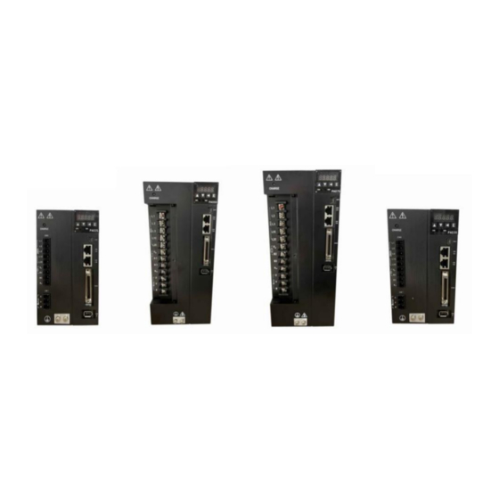
A-TS Technology RT20 3.1.2 Products appearance and dimensions Figure 3-1 RT20-PA010/015H Appearance and dimensions (Unit, mm) Figure 3-2 RT20-PA025/035H Appearance and dimensions (Unit, mm) Figure 3-3 RT20-PA050/075H Appearance and dimensions (Unit, mm) -
Page 15: Installation Direction
3.1.3 Installation direction Install the servo drive as the figure below. Good ventilation and heat dissipation must be ensured. Figure 3-4 RT20 series AC servo drive installation direction (Unit, mm) The drive should be mounted vertically on the base. - Page 16 >40mm >10mm >10mm >40mm Ventilate Figure 3-5 RT20 series AC servo drive installation space The working temperature should be below 45℃, to make sure the reliable performance. If the working temperature keeps above 45℃, please place the drive in the place with good ventilation.
-
Page 17: Wiring And Terminals
B2 and B3, and connect external resistor between the B1 and B2. Figure 3-6 RT20-PA pulse series AC servo drive wiring diagram Wiring operation should be performed by professional technicians. ... -
Page 18: Strong Power Terminals
Do not make mistakes in the connection terminals, otherwise it may cause cracks and damage. RT-STP is the Servo Tuning Program. It’s a debugging software provided by the A-TS Technology. For more details, please contact with us at www.a-ts.cn. 3.2.2 Strong power terminals 1. RT20-PA010/15/25/35 strong electricity terminals. - Page 19 A-TS Technology RT20 Table 3-1 RT20 series drive strong power terminals Terminal Name Specifications Labels Control power Connect to single-phase 380V AC power input terminals 380V (-15%)-440V (+10%) Main power Connect to three-phase 380V AC power supply input 380V (-15%)-440V (+10%)
- Page 20 L1/L2/L3 cannot be connected to single-phase 380V, but must be connected to three-phase 380V. Short-circuit L1C and L1, L2C and L2. 2. RT20-PA050/75 strong electricity terminals. Table 3-2 RT20-EA050/75 servo drive strong power terminals Terminal Name Specifications...
-
Page 21: Command Terminal Cn3
3.2.3 Command terminal CN3 Pulse sequence command mode RT20 command terminal CN3 includes pulse and direction input pins, digital input pins, digital output pins, and encoder feedback output pins. In the pulse sequence command mode, the pins on the terminal CN3 are as... - Page 22 RT20 Figure 3-7 the CN3 terminal It is recommended to use the original RT20 ac servo drive cable. The command terminals are MDR/SCSI-50 pins plug. Please confirm the pin sequence according to the solder side as the figure above.
- Page 23 A-TS Technology RT20 Digital input 4. The default function, DI4(NOT) reverse drive inhibiting input Digital input 5. The default function, mode DI5(M1-SEL) switch 1 input Digital input 6. The default function, mode DI6(M2-SEL) switch 2 input Digital input 7. The default function,...
- Page 24 A-TS Technology RT20 command Low-speed command, when the pulse OPC2 direction voltage is 12V or 24V, replace SIGN+. PULS+ Low-speed command pulse sequence input PULS- SIGN+ Low-speed command pulse direction input SIGN- AI1+ Analog command channel 1 input AI1-...
-
Page 25: Encoder Terminal Cn4/Cn5 Definition
Shielding / protection of the ground ground 3.2.4 Encoder terminal CN4/CN5 definition The RT20-PA series drive supports two encoder interfaces. The user can choose to use them according to the actual situation, or the encoder failure alarm may appear. 1) CN4 definition This terminal is used to input the servo motor encoder signal. - Page 26 This terminal is used to input the servo motor encoder signal. It can be connected to standard incremental encoder and ABZ incremental encoder only. The schematic diagram of encoder terminal pins is below. It is recommended to use the original accessory cable of the RT20 AC servo...
- Page 27 A-TS Technology RT20 drive. The encoder terminal is MDR/SCSI-20 core plug. Please confirm the pin sequence according to the solder side shown in the diagram below. Table 3-5 Standard incremental encoder signal input terminals Pin No. Signal Name...
- Page 28 A-TS Technology RT20 Without the permission or authorization by A-TS Technology, no motor or motor encoder shall be matched with RT20 servo drive. Otherwise, it may cause damage to the motor or even danger to personal safety. INSTRUCTIONS ...
-
Page 29: Usb Debugging Port Cn1 Definition
Encoder phase A signal input Encoder phase B signal input Encoder phase Z signal input Shield ground ABZ incremental encoder signal reference circuit RT20 servo drive incremental encoder AM26C32 AM26LS31 Figure 3-11 the ABZ incremental encoder input signal interface circuit 3.2.5 USB debugging port CN1 definition... -
Page 30: Rs485 Communication Port Cn2A/Cn2B Definition
This terminal is the standard RJ45 interface for RS485 bus communication. The RT20 series AC servo drive communicates with the controller through RS485 interface (adopting the Modbus protocol or Panasonic A5 driver communication protocol), to read and write parameters and monitor... -
Page 31: Wiring Of Three Control Mode
A-TS Technology RT20 the status. Please refer to the chapter 9 (Communication Function). The pins are defined as below. Signal Pin No. Description Port Definition Name CAN+ CAN bus data positive, reserved CAN- CAN bus data negative, reserved RS485+... - Page 32 A-TS Technology RT20 Note: L1C/L2C must be connected to the incoming Servo Motor terminal of the contactor RT20 Servo Drive Three-phase AC 380V Note:L1, L2 terminals connected To single-phase AC 380V DI-COM 3.3kΩ Servo enable DI1(SRV-ON) Alarm DO1+(SRDY+) D2(A-CLR)
- Page 33 A-TS Technology RT20 Note: L1C/L2C must be connected to the incoming terminal of the contactor Servo motor RT20 Servo Drive Three-phase AC 380V Note:L1, L2 terminals connected To single-phase AC 380V DO1+(SRDY+) Analog command Servo ready to output DO1-(SRDY-)...
-
Page 34: Display And Keyboard Operation
A-TS Technology RT20 4 Display and Keyboard Operation 4.1 Basic operation The operator panel adopts five LED tubes, two LED indicators, and four keys, as shown in the Figure 4-1. Figure 4-1 operation panel Five Led tubes LED works to display the states and parameters of the servo drive. -
Page 35: Menu Level One
A-TS Technology RT20 Page down, to display page, decrease serial number or value. Return key, Return or cancel. Enter key, Enter or OK. Two LED indicator PWR, it indicates that the drive main circuit is powered on. RUN, it indicates that the drive has already been enabled, and the motor is powered on. -
Page 36: Menu Level Two
A-TS Technology RT20 Menu level one Menu level two Monitoring Parameter setting Auxiliary function Auxiliary parameters Parameter management Motor parameter Motor running Figure 4-2 Menu level one 4.3 Menu level two Enter the menu level two by selecting the different menu level one. - Page 37 A-TS Technology RT20 Motor speed r/min Motor speed 1000 r/min Current position pulse Current position 1202345 Current position high eight-bit (×100000 Pulse) System position System position command command 345 pulse Servo internal position Servo internal position command pulse command pulse -17345...
-
Page 38: Parameter Setting (Pa/Fn Parameter)
If you modify PA84, you can press the Page down key. In the RT20 series servo, the PA menu only displays parameters up to parameter 99 by default. If it is old version, change the PA0 to 527, it will... -
Page 39: Parameter Management
A-TS Technology RT20 Parameter Parameter Parameter value increase Parameter value decrease Confirm Parameter modification PA98 Parameter PA99 Figure 4-6 PA parameter setting menu 4.3.3 Parameter management Parameter management mainly handles the operation between the parameter table and EEPROM. In the menu level one select and press the Enter key to go to the parameter management mode. - Page 40 A-TS Technology RT20 ② Reset to factory defaults The factory values of all parameters are read to the parameter table and written to the EEPROM parameter area. After power cycle, the factory default values of all parameters are applied.
-
Page 41: Speed Test Run
A-TS Technology RT20 Step 1. Select , or and press the Enter key. Step 2. Keep pressing the Enter key and hold for 3 seconds above. Digital tube will display , which indicates that the parameter is being written to the EEPROM. - Page 42 A-TS Technology RT20 JOG mode. The prompt of the JOG running is , and the Numeric unit is r/min. The system is in the speed control mode, and the speed command is set by parameter PA21. Press Page up key and hold, and the motor runs at the speed set by PA21.
-
Page 43: Commissioning And Running
A-TS Technology RT20 5 Commissioning and Running Trial running without load The purpose of trial running is to confirm whether the following items are correct. The servo drive power supply wiring The servo motor wiring Encoder wiring ... -
Page 44: Set Motor Type
INSTRUCTIONS The RT20 series servo drive can identify motor parameters for some motors from several manufacturers automatically, and need to identify motor parameters through codes for other manufacturers' motors. In the case that the two methods are not... - Page 45 A-TS Technology RT20 compatible, the motor parameters can only be identified through the user-defined method. Commissioning steps to automatic identification motor parameter Commissioning steps to identify motor parameters by code Set 00UEd in the Set PA61 to the Set PA1 to the...
-
Page 46: Speed Trial Running
A-TS Technology RT20 Change the PA0 ‘parameter password’ to 385, and press the Enter key to save. as the motor manufacturer type, and press the Enter key to save. Find the motor type code in the Motor Selection Guide, and set the PA1 parameter Motor type to this type code. -
Page 47: Jog Trial Running
A-TS Technology RT20 Factory Parameter Parameter Name value value description Control Speed of trial running mode control mode Lower 5 PA53 00001 00000 Drive enable digit input terminal Running forced ON First confirm there is no alarm or any abnormal condition. The motor is enabled at zero speed. - Page 48 A-TS Technology RT20 please check the wiring. Parameter setting Set the parameters according to the table below. Press page Motor runs Set to AU Press page Long press 01JOG mode Enter key The motor running speed is set by PA21.
-
Page 49: Position Control
Frequency division output Encoder frequency division output Figure 5-3 Position control block diagram 5.5.1 Position control simple example Wiring diagram for PLC Control Servo Motor RT20 Servo Drive 12-24V Servo enabled SRV-ON 29 (SON) 24v+ Position command PULS PULS- 24v+... -
Page 50: Position Command
Servo enabled SRV-ON (SON) CCWL /CN5 ALM+ Servo alarm output ALM- RT20 Servo Drive PULS Position command PULS PULS- 4 Note1: The X1 DI / DO port function SIGN+ 5 can be defined by t h e Position command SIGN paramete r . - Page 51 A-TS Technology RT20 Parameter Parameter Name Set value description Control mode Position control Electronic gear Appropriate PA12 Only valid when numerator value both PA81 and PA84 Electronic gear Appropriate are 0 PA13 denominator value 0: pulse+direction Position command PA14...
-
Page 52: Electronic Gear Setting
A-TS Technology RT20 Command pulse transmission path PA12 PULS Direction Input pulse Input pin Pulse f2=f1× M command f1 filtering SIGN mode PA52 Position PA15 command f2 Position Pulse command f3 PA19/PA24 Smooth mode filtering PA14 PA13 Electronic gear... -
Page 53: Speed And Torque Control
A-TS Technology RT20 5.6 Speed and torque control Speed control is applied where precise speed control is required. It’s can also be configured by the upper device. Torque feed forward Motor Input speed Speed Speed Speed command Speed Speed loop... -
Page 54: Rs485 Control Setting
A-TS Technology RT20 Speed value The proportional Appropriate Fn54 corresponding to relationship between value analog 10V voltage and speed Speed command transmission path PA27/Fn63/Fn64/Fn65 Digital value Speed setting Parameter PA40/41 PA36 command setting source Internal speed Smoot ACC/DE command... - Page 55 A-TS Technology RT20 RS485 0-no parity communication Appropriate 1-even parity PA87 verification method value 2-odd parity selection Each parameter is represented by 16 bits of data. The communication address of each parameter is determined by the parameter segment number and the parameter sequence number. The communication address has 16 bits of data, of which the high 8 bits are the parameter segment number and the low 8 bits are the parameter sequence number.
- Page 56 A-TS Technology RT20 parameters. 0x0300, motor speed, in unit rpm, consistent with dp00. 0x0301, current position (pulse), 16 bits low 0x0302, current position (pulse), 16 bits high 0x0303, position command (pulse), 16 bits low 0x0304, position command (pulse), 16 bits high...
- Page 57 A-TS Technology RT20 The speed and torque modes are switched over RS485, and the motor runs at a given speed. The steps are as follows. Set PA20 to 00010 (allow online switching of control modes) Set PA4 to 9 (Speed mode) ...
-
Page 58: Adjustment
A-TS Technology RT20 6 Adjustment 6.1 Summary The servo drive needs to drive the motor as fast as possible, and to track the commands from the upper machine or internal settings. To achieve it, the servo gain shall be adjusted reasonably. - Page 59 A-TS Technology RT20 circles movable stroke. ② Servo drive with the motor can work normally. ③ The motor and the load has been connected. The inertia identification process is as below. Set PA53 Set Fn69 Check the Input this value...
-
Page 60: Automatic Gain Adjustment
A-TS Technology RT20 6.3 Automatic gain adjustment By the rigid equivalence selection function (PA33), automatically the servo drive will generate a set of matched gain parameters to meet the requirements of speediness and stability. And it is the automatic gain adjustment. -
Page 61: Manual Gain Adjustment
A-TS Technology RT20 6.4 Manual gain adjustment 1) Purpose of the gain adjustment For commands from the upper controller, the servo drive makes the motor to work as instructed as possible without delay. In order to make the motor work as the commanded with the optimal mechanical performance, the servo gain adjustment is required. - Page 62 A-TS Technology RT20 filter suppresses mechanical resonance by reducing the gain of a specific frequency, and therefore the gain can be set higher. Parameters Fn45-Fn47 are the related to the notch filter. They are frequency, width level and depth level. When the frequency is the default value 1000HZ, the notch filter is actually invalid.
-
Page 63: Parameters
A-TS Technology RT20 7 Parameters 7.1 Parameter list The applicability column shows the applicable control mode. P means position control applicable, S means speed control applicable, T means torque control applicable, and ALL means it is applicable for position, speed and torque control all. - Page 64 A-TS Technology RT20 Speed proportional 2-2000 150* gain Speed integral time 1.0-1000.0 50.0* P, S constant Position proportional 1-1000 gain Speed feed forward PA10 0-200 gain Position command PA12 pulse frequency 1-32767 ★ division numerator Position command PA13 pulse frequency 1-32767 ★...
- Page 65 A-TS Technology RT20 direction NOT Bit2, Torque command direction NOT Bit3/4, rsv Position out of PA17 tolerance detection 0-3000 x 0.1 laps range Bit0, whether to use the battery Bit1, ABS source Absolute encoder 00000b-111 PA18 00101b Bit2, Motor...
- Page 66 A-TS Technology RT20 torque mode max speed PA22 Speed command ★ source selection User sets percentage PA23 of the maximum 1-200 ★ speed limit Torque command PA25 source selection Speed command PA26 0-3000 frequency setting Internal speed PA27 -9000-9000...
- Page 67 A-TS Technology RT20 bit0,high-speed pulse selection PA44 Pulse command 00000b-111 00000b ★ function selection bit1, get it by hand function The number of bits of Set to 0, means PA45 the absolute encoder 0-30 the default is 17 ★...
- Page 68 A-TS Technology RT20 Higher 5 bits input 00000b-111 PA54 00000b Binary terminal forced ON Lower 5 bits input 00000b-111 PA55 terminal NOT(logical 00000b Binary reverse) Higher 5-bits input 00000b-111 PA56 terminal NOT(logical 00000b Binary reverse) Output terminal 00000b-111 PA57...
- Page 69 A-TS Technology RT20 Bit0:Err18 Bit1:Err35 Alarm shield setting 00000b-111 PA62 00000b Bit2:Err41&6 bits Bit3:Err25 Bit4:Err8 Current proportional PA64 1-500 150* gain Current integration PA65 1-100.0 20.0* time constant PA69 External braking Ω 0-750 ★ resistor value PA70 External braking 0-10000 ★...
-
Page 70: Fn Parameters
A-TS Technology RT20 ★ command pulses per motor revolution UVW encoding PA90 corresponding to Z ★ pulse PA91 Incremental encoder ★ UVW direction PA93 System feedback Z ★ pulse polarity setting PA94 System feedback Z 0-15 ★ pulse width setting... - Page 71 A-TS Technology RT20 Digital input DI5 function 0-31 Digital input DI6 function 0-31 Digital input DI7 function 0-31 Digital input DI8 function 0-31 Set the point function corresponding to the digital IO input, the function codes are shown in the table below.
- Page 72 A-TS Technology RT20 Torque Reserved Torq_dir command direction setting Speed command Spd_dir Reserved direction setting Origin switch Origin trigger Org_sw Org_tog signal signal Absolute Org_set motor origin setting Parameter Factory Applica Name Unit range default bility Fn10 Digital output DO1 function...
-
Page 73: Bn Parameters
A-TS Technology RT20 NULL No definition SRDY Servo ready Servo alarm AT-POS Position arrival Brake action AT-SPD Speed reached Origin return HOME (homing) TQ_LMT Torque limiting complete Zero speed Origin (Home) Home detection position arrival The same DI function can’t be assigned to 2 or more IO input terminals, otherwise the alarm Err26 occurs. -
Page 74: Fault Alarm
A-TS Technology RT20 8 Fault Alarm 8.1 Alarm code list The alarm with ★ after the alarm code indicates that the alarm cannot be reset. To clear the alarm, the servo needs to be restarted. The digital tube shows Err x. x is the alarm code and can be viewed through the current interface of the digital tube. - Page 75 A-TS Technology RT20 9A/B/C phase error Err 10 Motor parameter Motor parameter is out of range ★ error Err 11 IPM module faulty IPM smart module is faulty ★ Err 12 Over current Motor current is too large Servo drive and motor are overloaded...
- Page 76 A-TS Technology RT20 Absolute encoder Battery voltage is lower than 3.1V, the battery Err 27 battery alarm voltage is low Absolute encoder Err 28 communication Feedback from the absolute encoder timed out timeout alarm Motor load exceeds the value and duration set...
-
Page 77: The End
A-TS Technology RT20 Internal D5V The voltage supplied to the control board is less Err 56 undervoltage than 5 V Motor speed out of There is large difference between command Err 62 control speed and actual speed. ABZ incremental... - Page 78 The contents of this document are to be updated without notice. Please contact us to get the latest version. ©A-TS Technology Copyright. All rights reserved. Published in Mar. 2023 Reprint or copy is strictly forbidden...
Need help?
Do you have a question about the RT20 and is the answer not in the manual?
Questions and answers