Advertisement
Quick Links
Date Created: 25/08/2016
Title: I.L.S. Control Cable Replacement
SAFETY!
the hazard identification table (section 3a of your Operator Manual) and take all necessary precautions.
Prior to continuing this procedure, isolate the power supply to the Pegasus I.L.S.
Firstly, switch the Tractor Ignition to the OFF position, then disconnect the I.L.S. Power Cable from the Tractor.
DO NOT work on live electrical equipment, as this is dangerous and may cause damage to electrical components
Circuitry supplied suits 12-VOLT NEGATIVE EARTH SYSTEMS ONLY!
Trimax or its agents will not be held liable for any damage or warranty claims occurring as a result of improper
Command Module exposed
Before attempting to make any adjustments or carry out maintenance on the mower, review
SPARE PARTS
INSTRUCTIONS # 30
Product: Pegasus S3 / Pegasus S4
Position the Pegasus on a smooth, hard and
level surface.
Ensure the surrounding area is clear of
obstructions and personnel.
Lower the Mower Decks down onto the
Ground.
and/or injury!
Caution:
wiring!
Remove the I.L.S. Cover from the Pegasus
expose the I.L.S. Command Module and allow
access.
This is located directly above the Pegasus
Chassis
4-Way Gearbox.
The process for this varies depending on which
model Pegasus you have, please refer to your
I.L.S. Operators Manal for instruction.
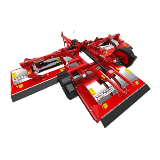
Note:
A Pegasus S4 is shown opposite.
Pegasus S4 requires the Main P.T.O Shaft to be
removed from the Mower! See your Operators
Manual!
1
Advertisement

Related Manuals for Trimax Pegasus S3

Summary of Contents for Trimax Pegasus S3
- Page 1 Caution: Circuitry supplied suits 12-VOLT NEGATIVE EARTH SYSTEMS ONLY! Trimax or its agents will not be held liable for any damage or warranty claims occurring as a result of improper wiring! Remove the I.L.S. Cover from the Pegasus expose the I.L.S.
- Page 2 Firstly, remove the six small screws from the the Top Cover of the Command Module. Note: This process can be achieved while the Command Module is still fitted to the Pegasus, there is no need to remove it! Lift the Top cover off of the Command Module.
- Page 3 Relay 3 Identify and trace the BLUE wire running from the I.L.S. Control Cable to Relay 3. Take note of the termination point of this wire, this is labelled on this Relay as POSITION 85. Slide the Spade Terminal off of the Relay to release the BLUE wire.
- Page 4 Feed the GREY wire and BROWN wire through the Inner Cable Gland Nut. One at a time, feed the BLUE wire and the Black Wire through the Inner Cable Gland Nut. One shown. Note: BLUE wire and the Black wire are a tight Remove Inner fit through the Inner Cable Gland Nut due to Cable Gland Nut...
- Page 5 Relay 4 Feed the BLACK wire running from the I.L.S. Control Cable to Relay 4. This is labelled on Relay 4 as POSITION 85. Slide the Spade Terminal onto the Relay Pin to secure the BLACK wire. Slide BLACK Wire Terminal onto Relay 4 Relay 3 Feed the...
- Page 6 Excess cable fed out Secure the Cable Gland Nut. of enclosure Tighten the INNER Cable Gland Nut to secure the Cable Gland to the Command Module Enclosure. Inner Gland Nut Loosen the Outer Cable Gland Nut. fitted Feed any excess I.L.S. Control Cable back out through the Cable Gland to the position shown.
- Page 7 This page is intentionally blank...
- Page 8 This page is intentionally blank...
Need help?
Do you have a question about the Pegasus S3 and is the answer not in the manual?
Questions and answers