Advertisement
Quick Links
Date Created: 31/05/2017
Title: Rotor Removal and Replacement
SAFETY!
Before attempting to make any adjustments or carry out maintenance on the mower, review
the hazard identification table (section 3a of your Operator Manual) and take all necessary precautions.
Due to the specialized nature of Rotor removal and replacement, it is recommended that this procedure is
only attempted at a fully equipped General Engineering Workshop.
Read through this entire process prior to starting. Take note of where parts are removed from!
Heavy Lifting Equipment is required for this process, ensure all Lifting Equipment is suitably rated!
REQURIED SHIM THICKNESS
Warlord Series 3 Mowers:
0.45 – 0.5mm (0.018 – 0.020") thick.
DRIVE END
Ensure all appropriate protective equipment is used.
SPARE PARTS
INSTRUCTIONS # 51
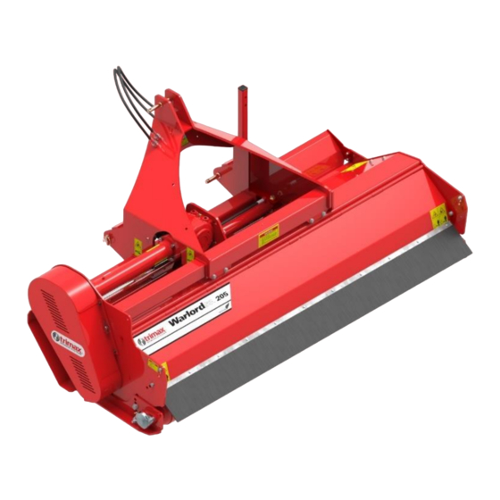
Product: Warlord S3
IMPORTANT:
Two strips of shim material are required for this
operation.
These should be a little longer than one side of the
square rotor bearing housing and about 10-15mm
(3/8 - 5/8") wide.
Use the Tractor hydraulics to position the
Headstock CENTRALLY in relation to the
Mower.
Disconnect the Warlord S3 and P.T.O Shaft from
the Tractor.
Remove the P.T.O Shaft from the Warlord S3.
This is detailed in the Operators Manual for the
Mower.
IMPORTANT:
A Warlord S3 175 Right-Hand Offset is shown
opposite, however this process applies for ALL
models and sizes.
The end with the Pulleys is ALWAYS referred to
as the DRIVE END. If your Warlord S3 is a
Left-Hand offset, the drive end will be
OPPOSITE to what is shown. However, the
process is IDENTICAL!
1
Advertisement

Related Manuals for Trimax Warlord 3 Series

Summary of Contents for Trimax Warlord 3 Series
- Page 1 SPARE PARTS INSTRUCTIONS # 51 Date Created: 31/05/2017 Product: Warlord S3 Title: Rotor Removal and Replacement SAFETY! Before attempting to make any adjustments or carry out maintenance on the mower, review the hazard identification table (section 3a of your Operator Manual) and take all necessary precautions. Due to the specialized nature of Rotor removal and replacement, it is recommended that this procedure is only attempted at a fully equipped General Engineering Workshop.
- Page 2 Remove the Rotor Bearing Guard from the NON-DRIVE end of the Mower as shown in YELLOW. Place the Rotor Bearing Guard and fasteners to one side. Remove Rotor Bearing Guard Remove the Belt Guard from the Drive-end of the Mower as detailed in the Operators Manual. Remove Belt Guard Remove the Belts as detailed in the Operators and Belts...
- Page 3 Remove Grub Screw Once the Taper Lock Bush has been driven off as far as possible, remove the Grub Screw. Taper Lock Bush driven as far as possible Insert a Flat Bladed Screwdriver into the Slot opposite the Removal Hole as shown. Use this to lever the Taperlock Bush open slightly.
- Page 4 Lower to this position Lower the Mower back down so that the TOP of the Headstock is now contacting the Ground and the Rotor is facing UPWARDS as shown. Note: The Mower may require some assistance to move past its tipping point. USE EXTREME CAUTION DURING THIS STEP! Sling Roller to...
- Page 5 Slacken the Rotor Bearing Locking Nut shown. DO NOT remove! Use a suitable section of Tube as a Drift to drive the Rotor Locking Nut and Taper Sleeve INWARDS towards the Rotor. This will release the Rotor Bearing from the Rotor Stub Shaft. Slacken Locking Nut, then Note: drive INWARDS...
- Page 6 Collect the replacement Rotor using suitable Lifting Equipment. Clean the Rotor Stub Shafts and ALL Rotor Bearing and Rotor Pulley Components using White Spirits and a Clean Cloth to remove contaminants. IMPORTANT: Position alongside the damaged Rotor. Ensure that the LONG Rotor Stub Shafts are BOTH facing the same direction.
- Page 7 Locking Nut in place Fit the Locking Nut to the Taper Sleeve. The Bevelled face of the Locking Nut MUST face TOWARDS the Rotor Bearing. Wind the Locking Nut on a few turns. DO NOT TIGHTEN! Repeat the above Bearing fitment process for the second Rotor Bearing Assembly.
- Page 8 Mount the NON-DRIVE END Rotor Bearing. Ensure the Grease Nipple is facing in the right direction before fitting the mounting bolts. FULLY TIGHTEN THE MOUNTING BOLTS. Ensure the fasteners are fitted as original! NON-DRIVE END Bearing in place Note: FULLY tighten mounting bolts A medium strength thread locker is required for use on the mounting bolts.
- Page 9 Hand tighten the NON-DRIVE END Locking Nut as tight as possible so the Taper Sleeve begins to lock onto the Rotor Shaft. Hand tighten the NON-DRIVE END Locking Nut as tight as possible Use a suitable “C” spanner to tighten the Locking Nut one half of a turn (180°) Note: If a “C”...
- Page 10 Slide the Bearing Assembly HARD up against the shims. DO NOT try to move the Bearing by tightening the bearing housing mounting bolts! If the Taper Sleeve locks up and prevents the Bearing from moving inwards, loosen the Locking Nut slightly and gently tap it inwards to release the taper.
- Page 11 Align one of the slots in the Locking Nut with the nearest tab on the Locking Washer. It may be necessary to tighten the Locking Nut slightly to achieve this. Bend the tab into the slot in the Nut to secure it. FULLY TIGHTEN THE DRIVE END MOUNTING BOLTS.
- Page 12 Lower to this position Lift the Mower until standing on its end. Lower the Mower back down so that the Headstock is facing UPWARDS as shown on the RIGHT. Note: The Mower may require some assistance to move past its tipping point. Lift to this USE EXTREME CAUTION DURING THIS position...
- Page 13 Adjust the position of the Extension Shaft Adjuster so that the Extension Shaft is running PARALLEL with the Mower Body. Extension Shaft Adjuster Note: Set Extension Shaft It is CRITICAL that the Extension Shaft is PARALLEL PARALLEL to the Body when fitting the Pulleys! This is to ensure the correct alignment of BOTH the Rotor and Gearbox Extension Pulleys! IMPORTANT:...
- Page 14 Check the Pulley alignment using a Long Straight Edge from the Extension Shaft Pulley. Ensure that the Straight Edge is positioned as shown opposite. Adjust the position of the Rotor Pulley so it is approximately 1mm (1/16”) INWARDS from the Straight Edge.
Need help?
Do you have a question about the Warlord 3 Series and is the answer not in the manual?
Questions and answers