
Related Manuals for Vela Treatment 87213


Summary of Contents for Vela Treatment 87213
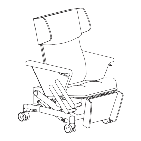
- Page 1 U S E R M A N U A L VELA Medical Manual. nr. 105634 Item no.: Model 87211 VELA Rumba 87212 VELA Neonatal chair 87213 VELA Treatment Chair *The chair’s design varies depending on the model...
-
Page 2: Table Of Contents
TABLE OF CONTENTS 1.0. INTRODUCTION 1.1. SAFETY 1.1.1. Safety Notes 1.1.2. Use 1.1.3. Transport 1.2. WARRANTY 1.3. UNWRAPPING THE CHAIR 1.4. MAINTENANCE 1.4.1. Wheels 1.4.2. Frame 1.4.3. Upholstery 1.5. RECYCLING AND DISPOSAL 1.6. PLACING/REMOVING PILLOWS 1.6.1. Footrest 1.6.2. Seat 1.6.3. Backrest 1.7. -
Page 3: Introduction
You can also find this user guide on VELA Medical’s website: www.vela-medical.com along with other relevant information about the chair. If you have any questions, please contact your VELA Medical dealer. We reserve the right to make changes. -
Page 4: Safety
:: The footrest is not designed to be sat This chair has CE certification and ap- upon. proval for the model name “VELA Rumba” and adheres to EU regulations. The chair :: The armrest is not designed to be sat adheres to all relevant Electromagnetic upon. -
Page 5: Use
VELA Medical. activated. VELA Medical is not liable for damages to All versions of the chair have been tested the product or the user arising from: :: Transport and approved for a maximum user weight of 140 kg. -
Page 6: Wheels
active chlorine, such as Actichlor All removable parts must be tightened Plus. We advise following the regularly. instructions on the packaging. 1.4.1. WHEELS We recommend checking and After cleaning/disinfection, the chair cleaning the wheels regularly to must be wiped down several times remove fluff, hair, and dirt. -
Page 7: Placing/Removing Pillows
1.6. PLACING/REMOVING PILLOWS 1.6.1. FOOTREST 1. Push the pillow against the footrest so the holes (1a) are pressed into the rubber brackets (1b). 2. Push the pillow firmly in place so that it cannot be moved up or down. 3. Click the cover (3a) onto the seat pillow (3b) to mount correctly. Note: there are buttons on both sides of the cover. -
Page 8: Quickguide - Remote Control
1.7. QUICKGUIDE – REMOTE CONTROL Before Use: The supplied blue ”key” must be used at the back of the hand control to turn from locked to open ”padlock”. This in order to use the chair’s electrical functions. Remote Control Can be placed on the side table or the bracket for the side table or behind the chair. Note: if the remote control is to be moved to the other side of the chair, this must always be done by bringing it behind the chair in order to avoid pinching hazards. -
Page 9: Settings
1.8. SETTINGS Modifications and repairs to the chair must only be carried out by a VELA Medical technician or a person with the required training. 1.8.1. USING THE BRAKES Press down on the brake pedal on the right or left side of the chair to apply the brake to the back wheels. -
Page 10: Using The Front Brakes
1.8.5. USING THE FRONT BRAKES* Double wheels with button-activated brakes. Press the buttons on the right and left side of the chair to engage brakes completely. Note: the button-activated brakes only engage two front wheels and should always be used with the pedal (Section 1.8.1.). 1.8.6. -
Page 11: Electrical Features
1.9. ELECTRICAL FEATURES Figure 1 Neutral/Lift down Lift up 1.9.1. LIFT (UP OR DOWN) The button on the left lowers the seat. The button on the right raises the seat (Figure 1). Warning! Beware of trapping hands or limbs underneath the chair when using the lift. Figure 2 Alighting assistance Neutral... -
Page 12: Backrest Angle
Figure 3 Neutral Maximum back angling 1.9.3. BACKREST ANGLE The button on the left angles the backrest forwards. The but- ton on the right angles the backrest backwards (Figure 3). Note: the backrest can only be serviced when the seat is in a horizontal position (Sections 1.7.2./1.7.4.). -
Page 13: Trendelenburg
Figure 5 Maximum back angling/footrest engaged Trendelenburg 1.9.5. TRENDELENBURG* The (red) button on the right angles the seating unit to Trende- lenburg (backrest horizontal, footrest up) (Figure 5). Note: not all chairs are equipped with the Trendelenburg feature! Figure 6 Trendelenburg Neutral 1.9.6. -
Page 14: Technical Data And Documentation
2.0. TECHNICAL DATA AND DOCUMENTATION 2.1. SPECIFICATIONS Maximum external measures (armrest and footrest horizontal): 180 cm x 81 cm (without side table) Weight: 91 kg Wheel size: 100 mm Minimum/maximum seat height: 47-87 cm Back angling: 43° (110°-153°) Trendelenburg back angling (additional purchase): Horizontal position, 0°... -
Page 15: Electromagnetic Emission
2.2. ELECTROMAGNETIC EMISSION RF emission CISPR 11, Group 1, Class A Harmonic Emissions IEC 61000-3-2, Class A Voltage changes/fluctuations and flickers IEC 61000-3-3 Immunity Test Test Level Professional Healthcare Electrostatic discharge (ESD) IEC 61000-4-2 ± 8 kV contact disharge ± 2,4,6,8,15 kV air discharge Radiated RF field IEC 61000-4-3 3 V/m 80 MHz –... - Page 16 VELA Medical :: Gøteborgvej 8-12 :: 9200 Aalborg SV :: Denmark :: Tel: +45 96 34 76 00 :: mail@vela-medical.com vela-medical.com...
Need help?
Do you have a question about the Treatment 87213 and is the answer not in the manual?
Questions and answers