Table of Contents
Advertisement
Quick Links
Advertisement
Table of Contents

Related Manuals for Gigabyte DO22-ST0


Summary of Contents for Gigabyte DO22-ST0
- Page 1 DO22-ST0 ORV3 Rack - 42OU 48V User Manual Rev. 1.0...
- Page 2 For GIGABYTE distributors and resellers, additional sales & marketing materials are available from our reseller portal: http://reseller.b2b.gigabyte.com For further technical assistance, please contact your GIGABYTE representative or visit https://esupport.gigabyte.com/ to create a new support ticket For any general sales or marketing enquiries, you may also message GIGABYTE server directly by email: server.grp@gigabyte.com...
- Page 3 Conventions The following conventions are used in this user's guide: NOTE! Pieces of additional information related to the current topic. CAUTION! Precautionary measures to avoid possible hardware or software problems. WARNING! Alerts to any damage that might result from doing or not doing specific actions.
- Page 4 Server Warnings and Cautions Before installing a server, be sure that you understand the following warnings and cautions. WARNING! To reduce the risk of electric shock or damage to the equipment: • Do not disable the power cord grounding plug. The grounding plug is an important safety feature.
- Page 5 Electrostatic Discharge (ESD) CAUTION! ESD CAN DAMAGE DRIVES, BOARDS, AND OTHER PARTS. WE RECOMMEND THAT YOU PERFORM ALL PROCEDURES AT AN ESD WORKSTATION. IF ONE IS NOT AVAILABLE, PROVIDE SOME ESD PROTECTION BY WEARING AN ANTI-STATIC WRIST STRAP AT- TACHED TO CHASSIS GROUND -- ANY UNPAINTED METAL SURFACE -- ON YOUR SERVER WHEN HANDLING PARTS.
- Page 6 Installing or removing jumpers: A jumper is a small plastic encased conductor that slips over two jumper pins. Some jumpers have a small tab on top that can be gripped with fin-gertips or with a pair of fine needle nosed pliers. If the jumpers do not have such a tab, take care when us- ing needle nosed pliers to remove or install a jumper;...
-
Page 7: Table Of Contents
Table of Contents Chapter 1 JBOD Hardware .....................8 Installation Precautions ..................8 Product Specifications ..................9 Chapter 2 Rack System Appearance ................10 System Front View ..................10 System Rear View ..................11 Management LAN Module LEDs ..............12 Power Supply Module LEDs ................13 Chapter 3 Rack System Hardware Installation .............14 Replacing the Power Supplies ............... -
Page 8: Chapter 1 Jbod Hardware
Chapter 1 JBOD Hardware Installation Precautions The motherboard/system contain numerous delicate electronic circuits and components which can become damaged as a result of electrostatic discharge (ESD). Prior to installation, carefully read the service guide and follow these procedures: • Prior to installation, do not remove or break motherboard S/N (Serial Number) sticker or warranty sticker provided by your dealer. -
Page 9: Product Specifications
Product Specifications NOTE: We reserve the right to make any changes to the product specifications and product-related information without prior notice. System Socket Security Server Operating Properties Š 600 (W) x 2223 (H) x 1068 (D) mm Dimension System fan Power Supply Open Rack Socket... -
Page 10: Chapter 2 Rack System Appearance
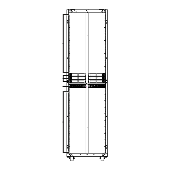
Chapter 2 Rack System Appearance System Front View Decription Upper Half Rack (18 Units / 25U-42U) Data LAN Switch (22U/23U/24U) Power Shelf with Power Supply Modules x 6 (21U) Lower Half Rack (20 Units / 1U-20U) System Appearance - 10 -... -
Page 11: System Rear View
System Rear View Decription Upper Half Rack (18 Units / 25U-42U) Data LAN Switch (22U/23U/24U) Power Shelf with Power Supply Modules x 6 (21U) Lower Half Rack (20 Units / 1U-20U) System Appearance - 11 -... -
Page 12: Management Lan Module Leds
Management LAN Module LEDs Name Color Description The power status of PMC. When PMC power up, it Power LED Green shall turn on; when system gets ready, it shall blink. Alert LED When warning or fault happens, it shall blink. Green/Red When find the location of PMC, these four led shall blink. -
Page 13: Power Supply Module Leds
Power Supply Module LEDs Status LED 1 Green Color (POWER) LED 2 RED Color (FAULT) AC_LOSS PSU fails event Solid RED Output 50V is ON Solid Green PSON OFF Blinking Green @ 2Hz (PSU is ready on) Bootloading Blinking RED@ 2Hz System Appearance - 13 -... -
Page 14: Chapter 3 Rack System Hardware Installation
Chapter 3 Rack System Hardware Installation Pre-installation Instructions Perform the steps below before you open the server or before you remove or replace any component. • Back up all important system and data files before performing any hardware configuration. • Turn off the system and all the peripherals connected to it. Replacing the Power Supplies CAUTION! •... -
Page 15: Replacing The Power Shelf
3-1-2 Replacing the Power Shelf Follow these instructions to replace the power shelf: Disconnect all power cables. Push the power module latch inwards and pull the power module out of its compartment. Remove all power supply units from the power shelf. Hardware Installation - 15 -... -
Page 16: Replacing The Lan Switch Tray
3-1-3 Replacing the LAN Switch Tray Follow these instructions to replace the lan switch tray: Disconnect all power cables. Push the switch latch inwards and pull the switch tray out of its compartment. Replace a switch tray into the cabinet until it clicks. Hardware Installation - 16 -... -
Page 17: Cable Routing
Cable Routing 3-2-1 Power Shelf to Data LAN Switch Cable Routing Rack Ports (Rear Side) Item Connect To LAN Switch (22U) Power Port LAN Switch (23U) Power Port LAN Switch (24U) Power Port Hardware Installation - 17 -... -
Page 18: Power Shelf To Ac Supply 3-Phase Connector Cable Routing
3-2-2 Power Shelf to AC supply 3-phase Connector Cable Routing Rack Ports Item Connect To AC supply 3-phase Connector Hardware Installation - 18 -... -
Page 19: Lan Cable Routing
3-2-3 LAN Cable Routing Switch Tray Ports Switch Tray to Management LAN Switch Switch Tray to Data LAN Switch Item Connect To Management LAN Switch Power Supply Connector Data LAN Switch Power Supply Connector Hardware Installation - 19 -...
Need help?
Do you have a question about the DO22-ST0 and is the answer not in the manual?
Questions and answers