
Related Manuals for AutoCrib ROBOCRIB TX750


Summary of Contents for AutoCrib ROBOCRIB TX750
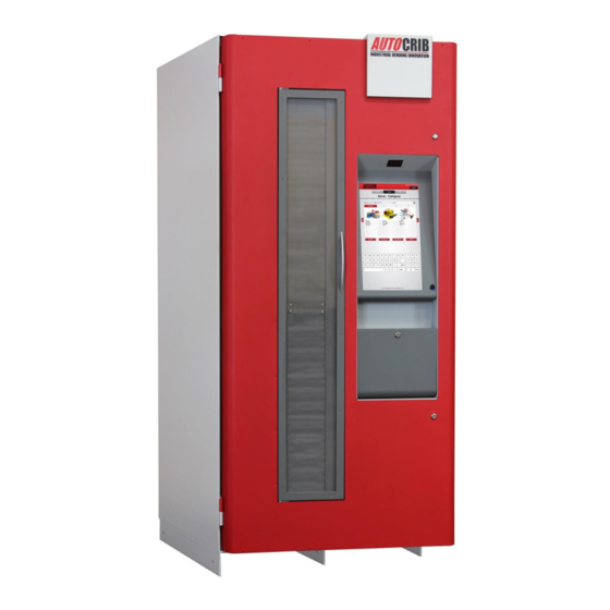
- Page 1 TX750 Operations Manual Last Revision December 2018 1-800-671-6501 | www.autocribsupport.com P a g e 1 | 90...
-
Page 2: Table Of Contents
Restore the Database ..........26 RoboCrib TX750 Software Configuration ........ 33 Create a Purchase Order and Tag ........35 Stock RoboCrib TX750 (Automatic Stock by Tag) ......37 Issue ............38 Manual Stock ........... 40 Physical by Bin ..........41 Physical All Bins .......... - Page 3 Issuing Items using Category, Family, and Type ......59 Using Category to Issue .......... 59 Commonly Performed Procedures ........60 Exiting RoboCrib TX750 software to access the Microsoft Windows desktop..60 Perform a Calibration Sequence ........60 Proper Loading Procedure ........61 Console Mode ..........
-
Page 4: Dispensing Machine Limited Warranty
You must indicate the RMA number on the box(es) that will contain any and all defective parts to be returned. If you do not provide the RMA number or fail to send the defective part back to AutoCrib you be charged for the defective part. - Page 5 AutoCrib will issue an offsetting credit to your company or authorized distributor per your instruction. Limitations and Exclusions: This warranty shall not cover or include any of the following and AutoCrib shall have no liability with respect to: Defects or damages which result from accident, misuse, abuse, lack of recommended or reasonable...
- Page 6 Machine Limited Warranty The foregoing warranty is in lieu of all other warranties, express or implied, and AutoCrib disclaims any warranties of merchantability and fitness for use or a particular purpose. This warranty is effective with AutoCrib installations beginning January 1, 2009.
-
Page 7: Equipment Supplied
Features Equipment Supplied • Complete RoboCrib TX750 • Battery Backup (Installed in units shipped within North America, Canada, and Mexico) • Adjustment Foot Set • Door Keys (4x) • Network Hub • CAT5 Cable, 25 feet • CAT5 Cable, 10 feet •... -
Page 8: Machine General Description And Features
“height” waste that is common with fixed door machines. Dramatically Reduce Maintenance Costs AutoCrib’s vast experience has found that reducing the number of moving parts significantly reduces maintenance. Utilizing a dual tambour eliminates over 15 separate sub-systems and greatly reduces maintenance costs. - Page 9 Features How it works 1. Login – Sign in using your employee badge or employee number. For additional security, require fingerprint validation. 2. Select Item – Select the item you want 3. 3. Dispense – The machine automatically finds the right item, opens the dual-tambour to dispense the product, and unlocks the outside security door.
-
Page 10: Repair Parts List
Features Repair Parts List PART # DESCRIPTION 170-430 Cable, Slip ring to Stack Motor, RTX 170-431 Cable Slip Ring to Controller, RTX 170-432 Cable Table Motor & Signal, RTX 170-433 Cable, Controller to upper tambour ref board, RTX 170-435 Cable, Controller to Lower Tambour ref board, RTX 170-520 Power Cord Assembly 20 feet with Ground Wire, 110/120VAC 183-001... - Page 11 Features PART # DESCRIPTION 329-916 Logo Panel, RTX750 372-653 Stack Arm Bearings 376-622 Shelf Retainer Bracket 376-631 Toggle Plate 376-669 Lead Screw 376-671 Door Guide Track 376-674 Bearing Block, Support Rod 376-678 Guide Rod 376-775 Plastic Shelf Removal Tool 376-805 Large Rectangle Shelf 376-805-2 Rectangle Retainer...
-
Page 12: Cautions
RoboCrib Setup & Installation Cautions The following cautionary information should be reviewed before the machine is installed. Following these requirements and warnings are required. CAUTION: This machine is designed for indoor usage only. Any other usage will void the Manufacturer’s Warranty. Voltage and Polarity Check It is important that this machine be hooked up to the proper voltage and polarity for your country. - Page 13 RoboCrib Setup & Installation P a g e 13 | 90...
- Page 14 RoboCrib Setup & Installation Tools Needed for Installation ▪ Outlet Tester (Can be purchased at Radio Shack or comparable electronics store.) ▪ Small ladder ▪ Forklift with adjustable forks ▪ 2 9/16” open end wrenches ▪ 3/4" open end wrench or adjustable wrench for leveling foot pad nuts ▪...
-
Page 15: Robocrib Tx750 Preparation
RoboCrib Setup & Installation RoboCrib TX750 Preparation The RoboCrib TX750 unit is assembled and packed so that a minimum amount of time is necessary for preparation to install it on location. The following steps are recommended to ensure correct unpacking. - Page 16 RoboCrib Setup & Installation TAKE CARE NOT TO PUSH ON THE FRONT DOOR OR TOUCH SCREEN WHEN MOVING THE MACHINE. WHENEVER POSSIBLE, USE A PALLET JACK INSERTED FROM THE FRONT OR BACK TO MOVE THE ROBOCRIB TX750. Fork Points P a g e...
-
Page 17: Installation
Place the RoboCrib TX750 in its final location and adjust the nuts, using a ¾” open-end wrench, to level the machine. d. Use a spirit level to make sure the RoboCrib TX750 is level on each side, then lock the nuts in place. -
Page 18: Routing Power & Network Connection
RoboCrib Setup & Installation Routing Power & Network Connection 6. Routing Power Cable - The system power cord is coiled and attached to the UPS with a 3- position detachable connector. The power can be routed through the top or bottom of the machine depending on where the power outlet is located. -
Page 19: Network Connection
RoboCrib Setup & Installation Network Connection 7. Run the CAT5 network cable (25ft provided with RoboCrib TX750) through one of the same routes as described for the power cord – up or down, depending on your preference. a. Connect the CAT5 cable to the computer’s Ethernet port. -
Page 20: Establish Power
RoboCrib Setup & Installation Establish Power 8. Locate the UPS located near the bottom right of the front door panel. Turn the UPS on by pushing the power button. Verify a green light appears on the UPS and the red building wiring fault LED on the top is off. - Page 21 9. Locate the power switch on the controller and move it to the “ON” position. The pc and touch screen monitor will boot. Press the ‘esc’ key (after Windows has launched) on the keyboard to avoid having the RoboCrib TX750 software launch. P a g e...
-
Page 22: Robocrib Tx750 In-Service Testing
RoboCrib Setup & Installation RoboCrib TX750 In-Service Testing 10. Use the Motor Switch Panel to test each motor. In order to use these buttons with the main door open, THE “DOOR OVERRIDE” button must be pressed in. a. Press the “TABLE” button together with the “DOOR OVERRIDE” button to move the Table motor until the red reference light blinks on and then off. -
Page 23: Setup Computer
Management Station Configuration Setup Computer 1. Connect the monitor using the blue VGA cable. 2. Connect the USB keyboard w/built-in trackpad. 3. Connect the network cable (CAT5) to the pc. Connect the other end of the network cable to the hub provided or LAN drop. - Page 24 4. Connect the power cables on the monitor and computer. If using hub, connect power cable as well. 5. Press the power button on the computer and monitor. 6. Turn off the AutoCrib software. 7. Ask the network administrator to properly configure the network LAN settings on the management station and RoboCrib TX750.
- Page 25 Management Station Configuration Dell Tower Ports Optical Drive Optical Drive Eject Button Optical Drive bay Media Card Reader (optional) USB 2.0 Connectors (2) Drive activity light Power button, power light Diagnostic lights (4) Headphone Connector Microphone Connector Network Connectivity Light Power Connector Back Panel Connectors Expansion Card Slots (4)
-
Page 26: Restore The Database
Management Station Configuration Restore the Database AutoCrib Software Must be Turned Off 1. Unzip the file database received from the AutoCrib Professional Services department into C:\Program Files\Microsoft SQL Server\MSSQL13.SQLEXPRESS\MSSQL\Backup on the AutoCab FX PC. 2. Start the Microsoft SQL Server Management Studio software. Connect to the server. (See Diagram 2.7) - Page 27 Management Station Configuration 3. Right Click on the Databases folder and click on Restore Database… 4. From the Source section select the Device radio button, then click the Browse button P a g e 27 | 90...
- Page 28 Management Station Configuration 5. Select the Add button within the Select backup devices screen 6. Navigate to the destination location of the .bak file and select the correct .bak file name, example: C:\ProgramFiles\MicrosoftSQLServer\MSSQL13.SQLEXPRESS\MSSQL\Backup\AutoCrib61.bak 7. Click the OK button P a g e 28 | 90...
- Page 29 Management Station Configuration 8. Select OK in the Select backup devices screen 9. From the Destination section of the screen select the name of the database to restore to from the Database dropdown field or if restoring to a new database, type in the new database name. P a g e 29 | 90...
- Page 30 Management Station Configuration 10. Within the ‘Backup sets to restore’ menu, verify that the “Restore” checkbox is selected 11. Within the ‘Select a page’ box click on Files, then within the ‘Restore database files as’ box check the Relocate all files to folder checkbox P a g e 30 | 90...
- Page 31 Management Station Configuration 12. Within the ‘Select a page’ box click on Options, then within the ‘Restore Options’ menu, check Overwrite the existing database checkbox and click OK 13. Click OK on message “Database “xxxxxx” restored successfully. P a g e 31 | 90...
- Page 32 CONGRATULATIONS! The database has now been restored and you are ready to begin using the AutoCrib software 14. Start the AutoCrib software NOTE: If the AutoCrib software prompts for the server, database name, username, and password, insert the following: Server: (LOCAL)
-
Page 33: Robocrib Tx750 Software Configuration
Insert Password: Rumen 2. Verify the RoboCrib TX750 computer is viewing correct data. a. Start the AutoCrib software by double clicking the shortcut available on the desktop. b. Login to the AutoCrib software using ‘admin’ as the username with no password. - Page 34 RoboCrib Software Configuration 3. In the Cribs > Tool Cribs screen, verify the RoboCrib TX750 is set as “1000-B”, the “Tambour” check box is selected, and “Config Stacks” are set to “All” 4. Add the RoboCrib TX750 computer as a controller.
-
Page 35: Create A Purchase Order And Tag
Stocking the RoboCrib TX750 Create a Purchase Order and Tag 1. Use the Robo New PO tab. This can be found in the Purchase Orders module within the Purchasing menu. 2. Select the crib, supplier, and method for reordering. 3. If all items should be ordered up to max, select “Purchase All”. Otherwise, insert the individual quantities into the Purchase field. - Page 36 Stocking the RoboCrib TX750 5. Create a Tag using the Create Tags tab. This can be found in the Purchase Orders module within the Purchasing menu. 6. Select the Purchase Order number created in step 3 by double clicking in the aqua field.
-
Page 37: Stock Robocrib Tx750 (Automatic Stock By Tag)
‘Yes’ → all items on the tag are available for stocking. ii. ‘No’ → some, but not all items on the tag are available for stocking. b. The RoboCrib TX750 will turn the platters until the first bin on the Inventory Input Sheet is in front of the door. -
Page 38: Issue
Software Operations Issue 1. At the RoboCrib TX7570, insert the badge number and PIN. 2. Select the Issue button. 3. Select appropriate responses from the blue validation tables. (i.e. Department, Job, etc.) and press Next P a g e 38 | 90... - Page 39 7. Press the Issue Now button to issue out the item, or press the Add to Cart button to issue out multiple items. 8. If the Issue Now button was selected, the RoboCrib TX750 will retrieve the bin and open the door. After removing the item, close the door and Logout of the software.
-
Page 40: Manual Stock
Manual Stock 1. At the RoboCrib TX750, insert the badge number and PIN. Note: At least one employee must be setup as a stocker in the AutoCrib software 2. Select the Stock -> Manual > Item buttons. 3. Search for the item. Once the item is highlighted, select ‘Restock’. (The system will only show items where the quantity in the RoboCrib TX750 is less than the item maximum.) -
Page 41: Physical By Bin
2. Select the Physical -> By Bin buttons. 3. Insert the Crib Number and Bin Number to physical. 4. After the RoboCrib TX750 retrieves the bin and the door opens, enter the correct on hand and/or burn quantities. Note: If you make no changes to the physical counts, the system will default to the current on hand and burn quantities. -
Page 42: Physical All Bins
Physical All Bins 1. At the RoboCrib TX750, insert the badge number and PIN. Note: At least one employee must be setup as a stocker in the AutoCrib software. 2. Select the Physical -> All buttons, then next to start. -
Page 43: Return
6. Place the item in the correct return location; regrind bin, active RoboCrib bin, or trash. Note: An item can only be returned to the RoboCrib TX750 if the crib has been designated as “returnable” in the AutoCrib software and the item being returned is a perishable, durable, kit, or gage type item. -
Page 44: Locate
Software Operations Locate 1. At the RoboCrib TX750, insert the badge number and PIN. 2. Select the Locate button. 3. Type in an item code or partial description of the item you wish to locate. Press Enter on the keyboard. -
Page 45: Maintain Module (Config Bin) - Assigning Bins
Maintain Module (Config Bin) – Assigning Bins 1. At the RoboCrib TX750, insert the badge number and PIN. Note: At least one employee must be setup as a supervisor in the AutoCrib software. 2. Select the Maintain, Config Bin, and Install and Assign Bins buttons. - Page 46 Software Operations 3. Use the bin layout diagram to select a column within a stack you would like to configure, then press Continue When the front door opens, click the Continue button from the Shelf Lock screen P a g e 46 | 90...
- Page 47 Software Operations 4. Select an empty space on the stack diagram for the bin Floor Position. 5. Enter the Bin Height or use the arrows to adjust and press Continue. P a g e 47 | 90...
- Page 48 Software Operations 6. Enter the Number of Bins you would like to configure. 7. Install the Bin Floors at the positions chosen. LED lights will illuminate the proper locations. Once complete press “Ok” button to continue. Note: To manually rotate the platter, press the “UNLOCK” button, thus unlocking the motor lock allowing for manual LP movement for 60 seconds.
- Page 49 Software Operations 8. Do you want to assign an item to the bin now? • If not, press No, and return the shelf locks to their home position and close the front door. • If yes, press Yes, and continue to Step 10. 9.
-
Page 50: Removing Center Walls For Xl Bins
Software Operations Removing Center walls for XL Bins 1. First, locate the center wall you would like to remove. 2. Use the manual buttons on the controller to move the Stack motor to remove screws corresponding to the wall desired to remove on both sides of it. 3. -
Page 51: Categorization
Type. A selection of Category will filter the selectable list of Families. A selection of Family will filter the selectable list of Types. A selection of Type will filter the list of items. Before this can be implemented, the categories and their associations must first be setup in the Autocrib software. Create Categories (See Diagram 5.7) -
Page 52: Create Families
Software Operations Create Families (See Diagram 5.8) 1. Create a Family by navigating to the Inventory -> Categorization -> Family tab in the AutoCrib software. 2. Select the Insert button. 3. In the Family Look-up box, enter a Category name and description. -
Page 53: Create Types
Software Operations Create Types (See Diagram 5.9) 1. Create a Type by navigating to the Inventory -> Categorization -> Type tab in the AutoCrib software. 2. Select the Insert button. 3. In the Type Look-up box, enter a Category name and description. -
Page 54: Associating A Family To A Category
Software Operations Associating a Family to a Category Within the Category tab, you can further classify item groups by associating families to each Category (See Diagram 5.10) 1. Highlight the Category in the View tab. 2. Select the Detail tab from the bottom of the screen. 3. -
Page 55: Associating A Type To A Family
Software Operations Associating a Type to a Family Within the Family tab, you can further classify item groups by associating types to each Family. 1. Highlight the Family in the View tab. 2. Select the Detail tab at the bottom of the screen. 3. -
Page 56: Associating An Item To A Type
Software Operations Associating an Item to a Type Within the Type tab, you can further classify item groups by adding Items to each Type. 1. Highlight the Type in the View tab. 2. Select the Detail tab at the bottom of the screen. 3. -
Page 57: Using Categorization At The Robocrib Tx750
Software Operations Using Categorization at the RoboCrib TX750 The steps above allow the user to display items through filtered lists in a Grid or Image view. Grid View At the Issue screen next to the View section press Grid View to view the Item list as a grid without images. -
Page 58: Image View
Software Operations Image View At the Issue screen next to the View section press Image View to view the Item list with images. (See Diagram 5.14) Diagram 5.14 P a g e 58 | 90... -
Page 59: Issuing Items Using Category, Family, And Type
Software Operations Issuing Items using Category, Family, and Type There are 4 buttons in the RoboCrib TX750 issue screen; Category, Family, Type, and Item. All four of these are used to find an item. Using Category to Issue (See Diagram 5.15) 1. -
Page 60: Commonly Performed Procedures
Exiting RoboCrib TX750 software to access the Microsoft Windows desktop. 1. Ensure the SuperRobo software is in the main login screen. 2. Double-click on the AutoCrib logo in the upper left portion of the screen. a. Insert the Exit username and press “OK”... -
Page 61: Proper Loading Procedure
Commonly Performed Procedures – Hardware and Software Proper Loading Procedure 1. Before installing the RoboCrib TX750, use the test shelves to select a proper bin size for the items. 2. ITEMS MUST NOT PROTRUDE FROM BIN TRAY PERIMETERS! Therefore, if an item does not fit easily into the bin, choose a larger bin size. -
Page 62: Console Mode
Console Mode 1. At the RoboCrib TX750, insert the badge number and PIN. Note: At least one employee must be setup as a supervisor in the AutoCrib software. 2. Select the Console button. 3. To Fetch a bin using this program type a command in this format “FET BBB UUUU LLLL” FET- Fetch command, B-Bin number, U-Upper tambour position, L-Lower tambour position. -
Page 63: Manually Fetch Bins And Open Doors Using Putty
Commonly Performed Procedures – Hardware and Software Manually Fetch Bins and Open Doors using Putty Note: The Putty program may not be connected to the controller at the same time as the SuperRobo software. 1. Exit the SuperRobo software. 2. Double Click the Putty shortcut from the desktop. 3. - Page 64 Commonly Performed Procedures – Hardware and Software 4. Click inside the big black text box and look for a solid green box if that is there you are connected, for verification just use the enter key a couple of times and you should get an -E1 this means you are connected successfully.
-
Page 65: Robocrib Controller Commands
Appendix RoboCrib Controller Commands PC Command Description Response Comments CC – Calibration Complete or CI – Calibration Incomplete FET abc ffff iiii Fetch Stall settings can be c – calibration status abc-Bin to be fetched adjusted using the CSn a-always 1 0-not calibrated since power-on commands. - Page 66 Appendix PC Command Description Response Comments Read Version Number Returns the version number and date of the software. CTB R nnn Read FLASH Table Returns xxxx, the value currently stored in FLASH location nnn. CONFIG state only Returns E1 error if not in CONFIG state. CTB U nnn xxxx Update FLASH Table Store value xxxx, into FLASH location nnn.
-
Page 67: Stall Settings
Appendix Stall Settings Further explanation of stall settings to be used with RSn [L/S/T] and CSn [L/S/T] commands: RSn L and CSn L • N=3 Stall setting used during ramp-up • N=8 Stall setting used during full speed • N=9 Stall setting used during slew or low speed just before brake •... -
Page 68: Explanation Of Errors On The Tx750
Appendix Explanation of Errors on the TX750 Calibration Errors C0 - This error will occur any time the machine is started or on a power loss to the controller. On normal operation the Touch screen will display the message “Machine will be calibrated”, press ok, the machine will start calibrating automatically while displaying the message “Calibrating Machine! Please Wait”. - Page 69 Appendix reference sensor 2. If the TABLE REF LED light stays on when the Reference tab passes the Reference Sensor – Visually inspect the Main Platter Reference Sensor damage (Distance between sensor and tab should be about 1 – 2 nickels width).
-
Page 70: Stall Errors
Appendix 2. Move the lower baffle all the way down using the push buttons on the controller and verify the LOWER TAMBOUR REF LED light turns from on to Stall Errors Error Action Message Code “Motor/Sensor Platter never 1. Use the controller moved manual switches to unresponsive... - Page 71 Appendix Move Cycle Speed Accel. Decel. Ramp Ramp Full speed part of move Check 2 Check 1 Fetch Fetch Ends Begins Time P a g e 71 | 90...
- Page 72 Appendix S Code Error Action Message “Motor/Sensor Platter started 1. Move the platter with the manual to move then switches and check for Jam unresponsive on platter X See Supervisor” stopped. 2. Check sensor board connections. Swap the sensor board from a functioning platter on another TX machine or spare parts.
- Page 73 Appendix S Code Error Action Message “Possible Jam on xxxx stall setting was 1. Check the machine for a product jam exceeded during 2. Once cleared re-calibrate Platter Supervisor” ramp-up part of move machine Move Cycle Accel. Speed Decel. Ramp Ramp Full speed part of move...
- Page 74 Appendix S Code Error Action Message “Close front door to continue.” Door open kept 1. Close the front door platter from moving 2. Verify complete latching of the or stopped it during a front door move Note: An S5 front door open error is caused by the front door open during or before platter movement. The system on detection will immediately stop the rotation of all platters as a safety hazard has occurred.
- Page 75 Appendix S Code Error Action Message “T or TU jammed see XXXX stall setting Contact technical support Supervisor” for tambour with door open ** XXXX Refers to the stall value that caused the stalls. Move Cycle Speed Accel. Full speed Decel.
- Page 76 Appendix S Code Error Action Message “Unexpected Object Stalls because hand Verify that the hand sensor jumper sensor detects blockage connections on the controller board Detected please hand sensor are connected and are intact remove to continue” connected) S Code Error Action Message...
- Page 77 Appendix S Code Error Action Message “Possible Jam on Platter xxxx stall setting was 1. Check the machine for a product X See Supervisor” exceeded for LP at end jam, once cleared re-calibrate the of move OR Tambour machine and verify a good fetch Gap Limit detected command (Lower and Upper...
-
Page 78: Care And Maintenance
Disconnect defective equipment from power immediately (unplug the equipment from the wall outlet). Any attempt by untrained persons to perform repairs may result in considerable hazards for the user. Important Note: If the equipment is still under warranty, contact AutoCrib Technical Support for repair/replacement instructions. -
Page 79: Preventative Maintenance
Care and Maintenance Preventative Maintenance Your RoboCrib TX750 has been designed to give you years of reliable service with a minimum amount of maintenance. However, some minor preventative maintenance is required to keep the system running in peak condition. Below we have listed the tasks that should be performed at periodic points to ensure the system performs at peak operating efficiency. -
Page 80: Hardware - After 30 Days
Care and Maintenance Hardware – After 30 Days Front Access Door • Open the Front access door using the FDUL/FDLK command. • Make sure the hinges and actuation systems are not binding up. If they are not working properly, make the necessary adjustments to ensure free operation. Lubricate with WD40 to flush out contaminants and eliminate binding. -
Page 81: Hardware - After 1 Year And Every Year Thereafter
Care and Maintenance Hardware – After 1 year and every year thereafter 1. Keep Front access door free of build-up 2. Clean the touch screen – DO NOT SPRAY DIRECTLY ON SCREEN!!! 3. Check for dropped product on the platter 4. -
Page 82: Robocrib Tx750 Technical Specifications
Technical Specifications RoboCrib TX750 Technical Specifications 1. Cabinet a. Width: 34-1/8” max. Height: 79” max (without feet or wheels) i. Fits through a standard office door ii. Will accept adjusting feet (included with machine) or optional wheels & floor anchors b. - Page 83 Technical Specifications iii. Interfaces cable from controller for power & signal iv. On-board LEDs indicate encoder status & ref mark sense, mirroring LEDs on controller g. Table Motor Cable – 8-position SL156 connectors on both the reference board and controller ends. Cable runs from reference board on the motor base bracket, up the front right edge of the cabinet, across access frame gap via the bulkhead holes, and terminates in header J2 on the controller.
- Page 84 J3. 8. Bin assemblies – refer to the RoboCrib TX750 Bin Layout diagram for profiles, bin positions & numbering a.
- Page 85 Technical Specifications i. Large Rectangular ii. Long Rectangular (combines two Large Rectangular with Center Wall removed) iii. Small rectangular iv. Triangular v. Filler Corner e. Two bin assembly profiles: i. Round – comprised of 2 large rectangular, 2 short rectangular, 4 triangular ii.
- Page 86 Technical Specifications ii. Filler Bin Assemblies – Bolted to top plate. Filler bin assemblies are also bolted to the table at the bottom with 4 ea. ¼-20 hex cap screws and split lock washers. 9. Front main door a. The main door secures the internal systems and stocked items. Access to the internal areas is via key locks.
- Page 87 Technical Specifications tambour bracket, and joins the bundle of other cables that cross the door gap at the bulkhead holes, traverse across the top channel, back across the door gap at the controller, where it is terminated in an 8-position connector on header J9 per pin-out. e.
- Page 88 Technical Specifications a. 120 individually addressable LEDs – 5 boards, 24 LEDs each. Boards are connected together via 7-conductor 22AWG cables with 7-position single-line .100 connectors at both ends. b. One LED Driver board is mounted to the face of the mounting bracket near the top tambour motor.
- Page 89 PC – Dell 790 Mini Desktop strapped to a mounting bracket viii. Signal cables are color coded for easy identification ix. PC is configured with AutoCrib software, and all appropriate and current drivers and executables d. UPS (Note: UPS Battery Backup is only provided with machines shipped within North America, Canada, and Mexico.
- Page 90 Technical Specifications xiii. Power supply – 90-250 VAC input, 24VDC output. AC power is fed from the power cord and attached to the AC input and ground points via ring terminals and screws per pin-out. The DC power cable is attached to the power supply with ring terminals &...
Need help?
Do you have a question about the ROBOCRIB TX750 and is the answer not in the manual?
Questions and answers