
Related Manuals for AutoCrib RoboCrib 2000 E


Summary of Contents for AutoCrib RoboCrib 2000 E
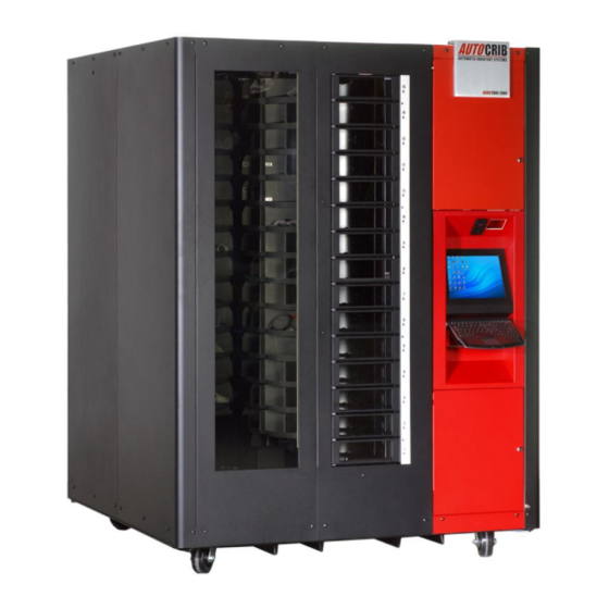
- Page 1 3011 S. CRODDY WAY, SANTA ANA, CA 92704 Phone: (800) 671-6501 RoboCrib 2000 Model E Operations Manual Last Revision July 2009...
- Page 2 Standard Warranty Period For a period of 12 months, following after the actual ship date from AutoCrib to the first purchaser of use. The warranty period covers all components, sub systems, and complete machines subject to the limitations and exclusions below.
- Page 3 AutoCrib will issue an offsetting credit to your company or authorized distributor per your instruction. Limitations and Exclusions This warranty shall not cover or include any of the following and AutoCrib shall have no liability with respect to: 1. Defects or damages which result from accident, misuse, abuse, lack of recommended or...
- Page 4 The foregoing warranty is in lieu of all other warranties, express or implied, and AutoCrib disclaims any warranties of merchantability and fitness for use or a particular purpose.
-
Page 5: Table Of Contents
Table of Contents FEATURES ..............................7 INSTALLATION ............................8 ................................. 8 AUTION ) ........8 OLTAGE AND OLARITY HECK ACHINES LOCATED IN ORTH MERICA ............................9 ETUP ......................13 ANAGEMENT TATION ONFIGURATION SOFTWARE OPERATIONS ........................19 ............................19 ANUAL TOCK .......................... - Page 6 Table of Contents TECHNICAL SPECIFICATIONS ......................... 35 ......................35 ECHNICAL PECIFICATIONS ........................35 XTERNAL ARTS ........................... 35 LATTERS .............................. 36 RIVE YSTEM ............... 36 OSTS HAFTS OUTING SSEMBLIES ........................37 ALIBRATOIN AND LIGNMENT ......................37 OORS AND AFFLE SSEMBLIES APPENDIX ..............................38 I ..............................
-
Page 7: Features
25 ft CAT5 cable 10 ft CAT5 cable 3 ft CAT5 cable Operating Instructions (this manual) Accessories Replacement Parts AutoCrib P/N Description AutoCrib P/N Description Baffle Assembly – Bottom 234-200 Battery Backup UPS 775-217-RP 760-103 CAT 5 Cable - 3 ft... -
Page 8: Installation
Installation Cautions The following cautionary information should be reviewed before the machine is installed. Following these requirements and warnings are required. CAUTION: This machine is designed for indoor usage only. Any other usage will void the Manufacturer’s Warranty. Voltage and Polarity Check It is important that this machine be hooked up to the proper voltage and polarity for your country. -
Page 9: Robocrib Setup
Installation RoboCrib Setup The AutoCrib unit is assembled and packed so that a minimum amount of time is necessary for preparation to install it on location. following steps are recommended to insure correct unpacking. 1. Shipping Damage: Thoroughly inspect the exterior of the crate and/or wrapping for damage, which may have occurred during shipment. - Page 10 Installation 7. Remove the safety shipping locks. They are tied together with a string to make them easy to identify. Remove the Top Arm Lock by removing the two 3/8 hex Top Arm Lock bolts that hold the lock bracket to the crossbar. bracket slides off the end of the stack support arm.
- Page 11 Attach the CAT5 cable from the NIC card (#4 on diagram) located at the bottom of the computer to the LAN drop provided by the customer (or to the Ethernet hub provided by AutoCrib). Once the connection has been made and the pc is started, the two lights on the NIC should blink.
- Page 12 Installation Check Platter Actuation 1. Test each motor clockwise (CW) and counter-clockwise (CCW) for a few seconds. Position the Direction switch in either the CW or CCW position. Then, activate the Motor Switch. Observe proper rotation. Then, reverse the Direction switch and test again.
-
Page 13: Management Station Configuration
Start the computer and have IT configure proper LAN settings. Turn off the AutoCrib software. STEP 2 – Restore the Database Unzip the file database received from AutoCrib‟s customer service department into C:\Program Files\Microsoft SQL Server\MSSQL.1\MSSQL\Backup. Start the Microsoft SQL Server Management Studio software. - Page 14 Installation Within the „Source for Restore‟ menu, enable “From Device”. Then, select the Browse button. Select the “Add” button within the „Specify Database‟ screen. Highlight the .BAK file saved in C:\Program Files\Microsoft SQL Server\MSSQL.1\MSSQL\Backup. Then, select “OK”. Select “OK” in the „Specify Backup‟ screen. Within the „Select the backup sets to restore‟...
- Page 15 Once the message “The restore of database „autocrib53‟ completed successfully” appears, select “OK”. CONGRATULATIONS!!! The database has now been restored and you are ready to begin using the AutoCrib software. Start the AutoCrib software. NOTE: If the AutoCrib software prompts for the server, database name, username, and password, insert the following.
- Page 16 Installation STEP 3 – Complete RoboCrib Setup Exit from the RoboCrib software on the RoboCrib. Click on the AutoCrib icon in the upper left hand corner. Insert Username: Rumen Insert Password: Rumen Verify the RoboCrib computer is viewing correct data.
- Page 17 If a supervisor has not yet been created, create a new employee in the Database > Employees module of the AutoCrib software and check “Supervisor” and “Stocker”. 2. Select the Console button in the RoboCrib software. At the command prompt, enter the “LON” command followed by each door number.
- Page 18 “Purchasing” report category of the Reports module. STEP 7 – Stock RoboCrib At the RoboCrib, insert the badge number and PIN. (Note: At least one employee must be setup as a stocker in the AutoCrib software.) Select the Stock > Auto > Tag buttons.
-
Page 19: Software Operations
When prompted, move the bin door bypass switch to TEST. Physically count the item(s) in the bins and document the quantities on the Physical by RoboCrib report located in the Reports module (Inventory category) of the AutoCrib software. 19 |... -
Page 20: Issue
Place the item in the correct return location; regrind bin, active RoboCrib bin, or trash. Note: An item can only be returned to the RoboCrib if the crib has been designated as “returnable” in the AutoCrib software and the item being returned is a perishable, durable, or gage type item. Locate At the RoboCrib, insert the badge number and PIN. -
Page 21: Troubleshooting The Robocrib Using The "Console" Button
Troubleshooting the RoboCrib using the “Console” Button At the RoboCrib, insert the badge number and PIN. (Note: At least one employee must be setup as a supervisor in the AutoCrib software.) Select the Console button. To call a bin, type FET BBB P (B is for Bin Number, P is for Baffle Position). i.e. FET 21L 3 will call bin 21L and set the baffle position for a fourth pie. -
Page 22: Commonly Performed Procedures - Hardware And Software
Exiting RoboCrib software on the touch screen to access the Microsoft Windows desktop. Ensure the RoboCrib software is in the main login screen. Double click on the AutoCrib logo in the upper left portion of the screen. Insert the Exit username and press “OK”... -
Page 23: Mttty
While lubricating a chain, you may want to have the platter move. Troubleshoot a specific problem with the machine When the Console mode is being used, no changes are made to the AutoCrib databases. Machine can move and open its bin access doors. MTTTY... -
Page 24: Troubleshooting
Troubleshooting Troubleshooting Common Problems Install or replace the touch screen display – Model C Only To remove the Display Assembly: Remove the Right Front Wall. This allows access to the display controller. Detach the DB9 cable and the power cord from the controller. Remove the wing nuts/nylocks that hold the display assembly to the Vertical Z channel. -
Page 25: Manual Switches Are Not Operational
Troubleshooting Manual Switches are not Operational Remove the Right Front panel. Manually rotate the Main platter with your hands until you have access to the LSP motor. Remove the protective box cover from the motor. Drive the motor back shaft (see diagram below) until you are able to access the correct tray assembly or small platter motor. -
Page 26: Problem: Receiving A Jam Or Stall Error, Finding Dropped Items
Troubleshooting Problem: Receiving a jam or stall error, Finding dropped items 1. Locate Source of Jam from Front Door Open the right front door with the key by turning both locks counterclockwise. Remove the left door hold-down screws using a #1 Phillips driver. ... - Page 27 Troubleshooting 2. Alternative Methods to Locate Jam If the source of the jam cannot be located from the front, use the key to open the top cover. Using a flashlight, look between the stacks to see if the source of the jam can be found. ...
-
Page 28: Problem: Motors Will Not Turn Or Leds On Controller Do Not Light Or Flash As They Should
If the headers are properly in place, use a voltmeter or continuity tester to verify the continuity of each lead back to its corresponding pin at the motor location. Call AutoCrib technical support for assistance. The headers and corresponding systems are: H1 –... -
Page 29: Problem: Door Does Not Open
Troubleshooting Problem: Door Does Not Open 1. Verify Power is OK The RoboCrib should be plugged into an active power outlet; the UPS status light should be green not beeping. Verify the RoboCrib power cord is plugged into UPS ... - Page 30 Turn the controller on and attempt to issue through the RoboCrib software. If the RoboCrib dispenses correctly, contact AutoCrib technical support to receive a replacement door. If the RoboCrib does not dispense correctly, contact AutoCrib technical support for further troubleshooting. ...
-
Page 31: Problem: The Led On Door Remains On
Turn the controller on and close the door. If the LED turned off, attempt to issue from the RoboCrib. If the RoboCrib dispenses correctly, no further troubleshooting is required. o If the LED does not turn off, use the spare door provided with the RoboCrib. Contact AutoCrib technical support to receive a replacement door. -
Page 32: Problem: Open Door Error Message Or Led Does Not Turn On When Door Is Open
Troubleshooting Problem: Open Door error message or LED does not turn on when door is open 1. Test all doors using Console screen Login to the RoboCrib software as a supervisor and select the Console button. Actuate each individual door by using the LON ## command (## - Representing the door number) ... -
Page 33: Preventative Maintanence
Clean the keyboard with a keyboard cleaner. DO NOT place any liquid into the keyboard. This may damage the internal workings of the keyboard. AutoCrib suggests cleaner be applied to a rag before wiping the keyboard. Touch Screen Wipe the screen with a clean, soft rag. - Page 34 Preventative Maintenance Repeat this process for the LSP and the 3 SSP chains. These chains are adjusted by loosening the motor mount bolts. Tighten the chains by moving the motor mounts outward. Hardware – After 1 year and every year thereafter Keep bin doors free of build-up Clean the touch screen –...
-
Page 35: Technical Specifications
Technical Specifications RoboCrib Technical Specifications RoboCrib External Parts Frame A 2” steel tube frame supports a chain drive system, which actuates 12 individual platters. The frame is 62” wide, 62” deep, and 83” high (including wheels). Wheels Omni-Directional Non-Locking Leveling footpads are included with the shipment of the RoboCrib if using the wheels is not preferred. Walls Made from 16Ga steel Sit in a channel, lock together with interlocking tabs, and attach to the frame by pin-in-hex tamper-... -
Page 36: Drive System
Technical Specifications Drive System Motors Electric Gear Motors 3 sizes Main Motor (1 each) Large Sub Platter Motor (1 each) Small Sub Platter Motor (3 each) Encoders and Position Sensors – Hall effect slotted interrupts Encoders Main and Large Sub Platter: located on the motor backshaft ... -
Page 37: Calibratoin And Alignment
The calibration sequence resets the “home” position for the RoboCrib program to bin 111. NOTE: If bins do not align correctly, contact AutoCrib for instructions on fine-tuning the machine. Bin Doors and Baffle Assemblies Bin Doors: There are 15 levels of delivery doors. -
Page 38: Appendix
Appendix Appendix I RoboCrib Controller Commands c – calibration status FET abc d Fetch command The stall values can be abc-Bin to be fetched 0-not calibrated since power on adjusted using the CSn 1-calibrated commands. If a stall a-LSP number -2-encoder B error so internal position is wrong recurs several times b-SSP number... -
Page 39: Ppendix Ii
Appendix Appendix II Explanation of Errors on a RoboCrib Calibration Errors C Code Error Action Message “Recalibrating Not calibrated Check pot voltage for wind Please Wait” Since start up Count and recalibrate. Notes: This error will occur any time the machine is started or on a power loss to the controller. On normal operation, the Touch screen will display an error noted above and check the pot voltages. - Page 40 Appendix C Code Error Action Message “Ref Tab not detected on Platter Check the wind count and Attempt to platter X see supervisor” mark recalibrate 3 times with no error. detected. unsuccessful throw error and lock touch screen. Notes: When a C3 error occurs, the affected platter did not detect the magnetic indicator on the platter (MP) or the chain.
-
Page 41: Jam Errors
Appendix Jam Errors S Code Error Action Message “Motor/Sensor Platter never 1. Take no action moved 2. Throw error unresponsive on platter X See Supervisor” sensors 3. Lock the screen. connected. Move Cycle Speed Accel. Decel. Ramp Ramp Full speed part Of move Check 2 Check 1... - Page 42 Appendix S Code Error Action Message “Motor/Sensor Platter 1. Take no action started 2. Throw error unresponsive on platter X See Supervisor” move then 3. Lock the screen. stopped/. Move Cycle Speed Accel. Decel. Ramp Ramp Full speed part Of move Check 2 Check 1 Fetch Begins...
- Page 43 Appendix S Code Error Action Message “Possible Jam on Platter r Platter 1. Take no action X See Supervisor” slow during 2. Throw error full speed 3. Lock the screen. part of the move. Move Cycle Speed Accel. Decel. Ramp Ramp Full speed part Of move...
- Page 44 Appendix S Code Error Action Message “Possible Jam on Platter r Unexpected 1. Take no action X See Supervisor” Platter 2. Throw error deceleration 3. Lock the screen. during full speed part of the move. . Move Cycle Speed Accel. Decel.
- Page 45 Appendix S Code Error Action Message “Close the lighted door” Door opens 1. Throw error during Platter 2. Wait for door to close movement. 3. Refetch the called Bin Move Cycle Speed Accel. Decel. Ramp Ramp Full speed part Of move Check 2 Check 1 Fetch Begins...
- Page 46 Appendix S Code Error Action Message “S6 Baffle Jammed Baffle 1. System moves to position 5 working 2. Refetch the called Bin See Supervisor” jammed. 3. If still S6 then throw error and lock is bad screen Move Cycle Speed Accel.
- Page 47 Appendix S Code Error Action Message “S7 Overwind condition Wrap 1. System cuts power to MP motor and See Supervisor ” voltage limit LSP motor. hit- Power to 2. Throw Error MP and LSP 3. Lock Screen motors cut. This most likely occurs on while using manual switches.
- Page 48 Appendix S Code Error Action Message “S8 Possible System Check wind count Attempt Platter X See Supervisor” failed recalibrate 3 times with no error and accelerate refetch. If unsuccessful throw error and to required lock touch screen. speed check point Move Cycle Speed Accel.
- Page 49 Appendix S Code Error Action Message “S9 Possible System 1 Check wind count and Attempt to Platter X See Supervisor” failed recalibrate 3 times with no error and accelerate to refetch. If unsuccessful throw error and required lock touch screen. speed check point Move Cycle...
-
Page 50: Door Maintenance
Appendix Door Maintenance 1/10/2005 Bulletin No: 1002 Products Affected: RoboCrib 1000 RoboCrib 2000 Summary: Bin door lubricating procedure Description of Issue: Standard maintenance change bin door lubricating procedures. In effort to reduce the number of difficulties in closing bin doors as well as reducing the number of bin doors that intermittently do not open when actuated. - Page 51 Appendix 51 | P a g e...
- Page 52 Appendix 52 | P a g e...
-
Page 53: Care And Maintenance
The built-in power supply no longer functions properly Important Note: If the equipment is still under warranty, The device has been stored for a relatively long contact AutoCrib Technical Support for repair/replacement period under unfavorable conditions (e.g., extreme instructions. moisture)
Need help?
Do you have a question about the RoboCrib 2000 E and is the answer not in the manual?
Questions and answers