Advertisement
Helvest
Operating instructions for the Helvest
1. General product presentation
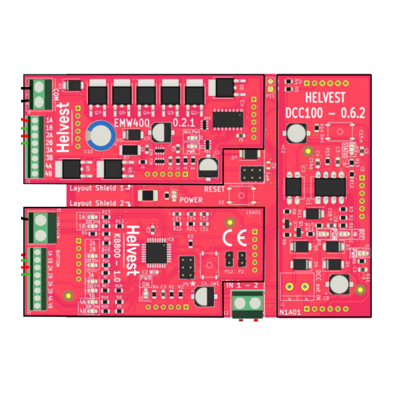
1.1 KB800 module for push button interfacing
The KB800 board controls digital accessories (such as switches or signals) via
pushbuttons alongside digital control via the control unit or PC.
It is a Layout module for the HP100 motherboard and works in conjunction with
another Layout module that controls the accessories.
An example of use is shown in figure 1: the "Layout 1" module can be any module
of the Helvest FleX system and controls 4 accessories (turnouts or signals). These
can be controlled either by DCC ( through the DCC100 card) or by buttons
connected to the KB800 module.
This can be useful to move turnouts or signals locally in the station (e.g. to perform
shunting), or to test accessories during programming or during installation.
The KB800 module must be inserted in a "layout" slot on the HP100 board and is
automatically recognised by the board. The system recognises the KB800 module
and the other module that controls the accessories on the same board and
automatically associates them. No matter which one is in position "1" and which one
is in position "2", they can also be swapped with respect to the example in fig. 1.
To insert the module, switch off the power to the HP100 board, ensure that the
connectors are aligned and apply gentle pressure until the module is fully inserted
into the slot.
1.2 Mounting the PCB on the layout
The complete board must be mounted in such a way that it DOES NOT touch
anything during operation. In particular, it must not come into contact with any
metallic or flammable material.
For temporary installations, it can be placed on a non-flammable insulating surface
(plastic,glass, ceramic floor, etc...).
®
FleX KB800 board
FleX Layout module KB800 - User Manual
P1
1A
1B
P2
Layout 1 - Module
COM
2A
P1
2B
P2
COM
1A
1B
2A
2B
KB800
3A
3B
4A
4B
Your DCC central
Ihre DCC Zentrale
Fig. 1
DCC100
Advertisement
Table of Contents

Related Manuals for Helvest Flex KB800

Summary of Contents for Helvest Flex KB800
- Page 1 This can be useful to move turnouts or signals locally in the station (e.g. to perform shunting), or to test accessories during programming or during installation. The KB800 module must be inserted in a "layout" slot on the HP100 board and is automatically recognised by the board. The system recognises the KB800 module and the other module that controls the accessories on the same board and automatically associates them.
-
Page 2: Dcc Operation
1 can be used indifferently (the one with the solid line or the one with the hatching in fig. 4). Programming the KB800 module is not necessary. Of course, the addresses of the other installed module must be programmed for operation via the control unit. -
Page 3: Examples Of Use
1. Disconnect the decoder power supply; 2. Remove the module that you do not want to test, and insert a KB800 module in If the above measures do not work, please contact us via the form on helvest.ch. its place: in fig. 5 it is assumed that you want to test the accessories connected to the "Layout 1"... -
Page 4: Technical Specifications
Helvest FleX Layout module KB800 - User Manual 4 . TECHNICAL SPECIFICATIONS Firmware HP100 >1.2 Board type: module for accessory control via push buttons, for HP100 motherboard. Instruction manual rev. 1.0 (2021). Input power for logic circuit: 5V DC, from motherboard. - Page 5 Helvest FleX Layout module KB800 - User Manual...
Need help?
Do you have a question about the KB800 and is the answer not in the manual?
Questions and answers