Advertisement
Package Contents
- Managed 26-Port FE PoE Switch (ES-3026P) or
Managed 24-Port GE Switch (ES-3024G) or
Managed 24-Port GE PoE Switch (ES-3024GP) - RJ-45 to RS232 Console Cable
- Four Adhesive Foot Pads
- Two Brackets and Eight Screws
- One Ground Screw
- Quick Installation Guide (QIG)
- Manual CD
 Note: Power Cord is separately supplied for the product with the suffix of "*.STGDLN"
Overview
ES-3026

ES-3026P

ES-3024G

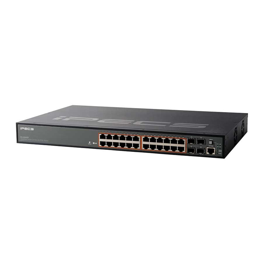
ES-3024GP

The iPECS ES-3000/3000G is a family of fully managed Layer 2 switches that support enterprise-class Layer 2 switching features including advanced QoS, security and simplified and intuitive management features allowing network administrators to build high performing robust network affordably.
The iPECS ES-3000 series comes in 4 models from Fast Ethernet to Gigabit Ethernet. The ES-3026 and ES-3026P are Fast Ethernet Layer 2 switches with 24 10/100 BASE-TX ports, and two Small Form Factor Pluggable (SFP) transceiver slots that operate in combination with 10/100/1000 BASE-T ports 25 ~ 26. The ES-3024G and ES3024GP are Gigabit Ethernet Layer 2 switches with 24 10/100/1000 BASE-T ports, and four Small Form Factor Pluggable (SFP) transceiver slots that operate in combination with ports 21~24. The ES-3026P and ES-3024GP also provide PoE power to connected devices.
Installing the Switch
Selecting a Site
- The site should:
- be at the center of all the devices you want to link and near a power outlet.
- be able to maintain its temperature within 0 to 50°C (32 to 122°F) and its humidity within 10% to 90%, non-condensing.
- provide adequate space (approximately two inches) on all sides for proper air flow.
- be accessible for installing, cabling and maintaining the devices.
- allow the status LEDs to be clearly visible.
- Make sure twisted-pair cable is always routed away form power lines, fluorescent lighting fixtures and other sources of electrical interference, such as radios and transmitters.
- Make sure that the units is connected to a separate grounded power outlet that provides 100 to 240 VAC, 50 to 60 Hz, is within 2 m (6.6 feet) of each device and is powered from an independent circuit breaker. As with equipment, using a filter or surge suppressor is recommended.
Rack Mounting
The switch can be mounted in a standard 19-inch equipment rack.
Before rack mounting the switch, pay particular attention to the following factors:
- Temperature: Since the temperature within a rack assembly may be higher than the ambient room temperature, check that the rack-environment temperature is within the specified operating temperature range. (0°C to 50°C)
- Mechanical Loading: Do not place any equipment on top of the rack-mounted unit.
- Circuit Overloading: Be sure that the supply circuit to the rack assembly is not overloaded.
- Grounding: Rack-mounted equipment should be properly grounded. Particular attention should be given to supply connections other than direct connections to the mains.

To rack-mount devices:
- Step 1: Attach the brackets to the device using the screws provided in the Bracket Mounting Kit.

- Step 2: Mount the device in the rack, using four rack-mounting screws (not provided).
Be sure to secure the lower rack-mounting screws first to prevent the brackets from being bent by the weight of the switch.

- Step 3: If installing a single switch only, go to "3. Powering Up".
- Step 4: If installing multiple switches, mount them in the rack, one below the other.


Desktop or Shelf Mounting

- Step 1: Attach the four adhesive foot pads to the bottom of the first switch.
- Step 2: Set the device on a flat surface near an AC power source, making sure there are at least two inches of space on all sides for proper air flow.
- Step 3: If installing a single switch only, go to "3. Powering Up".
- Step 4: If Installing multiple switches, attach four adhesive foot pads to each one. Place each device squarely on top of the below.
Installing an Optional SFP Transceiver
The SFP slots support the following optional SFP transceivers:
- 1000BASE-SX
- 1000BASE-LX
- 1000BASE-LH
- 100BASE-FX

To install an SFP transceiver, go the following:
- Step 1: Considering network and cabling requirements to select an appropriate SFP transceiver type.
- Step 2: Insert the transceiver with the optical connector facing outward and the slot connector facing down. Note that SFP transceivers are keyed so they can only be installed in one orientation.
- Step 3: Slide the SFP transceiver into the slot until it clicks into place.
Note: SFP transceivers are hot-swappable. The switch does not need to be powered off before installing or removing the transceiver. However, always first disconnect the network cable before removing the transceiver.
Note: SFP transceivers are not provided in this switch package.
Powering Up
Connect the AC power cord to the back of the switch, and then connect the cord to an AC power outlet.

Port and System Status LEDs
The switch includes a display panel for system status and port indications that simplify installation and network troubleshooting. The LEDs, which are located on the front panel for easy viewing, are shown below and described in the following tables.
ES-3026P

ES-3024GP

ES-3026/3026P Fast Ethernet Switch Port Status LEDs
| LED | CONDITION | STATUS |
| Fast Ethernet Ports (1 ~ 24) | ||
| LNK/ACT | Amber Amber Flashing | An amber LED indicates that the port is operating at 10 Mbps. It flashes when the corresponding port is active. |
| Green Green Flashing | A green LED indicates that the port is operating at the maximum speed 100 Mbps. It flashes when the corresponding port is active. | |
| Off | There is no valid link on the port. | |
| SFP Gigabit Ethernet Ports (25 ~ 26) | ||
| LNK/ACT | Amber Amber Flashing | An amber LED indicates that the port is operating at 10/100 Mbps. It flashes when the corresponding port is active. |
| Green Green Flashing | A green LED indicates that the port is operating at the maximum speed 1000 Mbps. It flashes when the corresponding port is active. | |
| Off | There is no valid link on the port. | |
ES-3024G/3024GP Gigabit Ethernet Switch Port Status LEDs
| LED | CONDITION | STATUS |
| Gigabit Ethernet Ports (1 ~ 24) | ||
| LNK/ACT | Amber Amber Flashing | An amber LED indicates that the port is operating at 10/100 Mbps. It flashes when the corresponding port is active. |
| Green Green Flashing | A green LED indicates that the port is operating at the maximum speed 1000 Mbps. It flashes when the corresponding port is active. | |
| Off | There is no valid link on the port. | |
| SFP Ethernet Ports (21 ~ 24) | ||
| LNK | Green | It indicates that a SFP transceiver is inserted. |
| Off | There's no SFP transceiver inserted. | |
ES-3000/3000G Switch System Status LEDs
| LED | CONDITION | STATUS |
| PWR | Green | Internal power operates normally |
| Off | No power supply plugged | |
| Diag | Amber | System Diagnostic in progress |
| Amber Flashing | System Diagnostic Fail | |
| Green | System Diagnostic test OK | |
| Green Flashing | It flashes while booting. | |
| PoE (When Mode button pressed) | Amber | It indicates that the port's LEDs display PoE status. |
| Amber Flashing | It indicates that power budget reached maximum value or power budget under and including 95% for whole system. |
Conneting to the Switch
Using Console Port
Attach a VT100-compatible terminal, or a PC running a terminal emulation program to the switch. You can use the console cable provided with this package.
To connect a terminal to the console port, complete the following steps:
- Step 1: Connect the console cable to the serial port on a terminal, or a PC running terminal emulation software, and tighten the captive retaining screws on the DB-9 connector.
- Step 2: Connect the other end of the cable to the RS-232 serial port on the switch.
- Step 3: Make sure the terminal emulation software is set as follows:
- Select the appropriate serial port (COM port 1, or COM port 2, ...).
- Select the baud rates to 115200 bps.
- Select the data format to 8 data bits, 1 stop bit, and no parity.
- Set the emulation mode to VT100.
- When using HyperTerminal, select Terminal keys, not Windows keys.
Accessing the CLI
To access the switch through the console port, perform the following steps:
- Step 1: At the console prompt, enter the user name and password. (The default user names are "admin" and "guest" with corresponding passwords of "admin" and "guest".) When the administrator user name and password is entered, the CLI displays the "ES-3026#" prompt and enters privileged access mode. But when the guest user name and password is entered, the CLI displays the "ES-3026>" prompt and enters normal access mode.
- Step 2: Enter the necessary commands to complete your desired tasks.
- Step 3: When finished, exit the session with the "quit" or "exit" command.
After connecting to the system through the console port, the login screen displays:
| User Access Verification CLI session with the ES-3026 is opened. ES-3026# |
Setting IP Address
You must establish IP address information for the stack to obtain management access through the network. This can be done in either of the following ways:
- Manual: You have to input the information, including IP address and subnet mask. If your management station is not in the same IP subnet as the stack's master unit, you will also need to specify the default gateway router.
- Dynamic: The switch can send IPv4 configuration requests to BOOTP or DHCP address allocation servers on the network.
To assign an IPv4 address to the switch, complete the following steps:
- Step 1: From the Global Configuration mode prompt, type "interface vlan 1" to access the interface-configuration mode. Press <Enter>.
- Step 2: Type "ip address ip-address netmask", where "ip-address" is the switch IP address and "netmask" is the network mask for the network. Press <Enter>.
- Step 3: Type "exit" to return to the global configuration mode prompt. Press <Enter>.
- Step 4: To set the IP address of the default gateway for the network to which the switch belongs, type "ip default-gateway gateway", where "gateway" is the IP address of the default gateway. Press <Enter>.
| ES-3026(config)#interface vlan 1 ES-3026(config-if)#ip address 192.168.1.1 255.255.255.0 ES-3026(config-if)#exit ES-3026(config)#ip default-gateway 192.168.1.254 |
Setting Password
Passwords can consist of up to 8 alphanumeric characters and are case sensitive. To prevent unauthorized access to the switch, set the passwords as follows:
- Step 1: Open the console interface with the default user name and password "admin" to access the privileged access mode.
- Step 2: Type "configure" and press <Enter>.
- Step 3: Type "username guest password 0 password", for the normal access mode, where "password" is your new password. Press <Enter>.
- Step 4: Type "username admin password 0 password", for the privileged access mode, where "password" is your new password. Press <Enter>.
| Username: admin CLI session with the ES-3026 is opened. ES-3026#configure |
Connecting to the Web Interface
Prior to accessing the switch from a web browser, be sure you have first performed the following tasks:
- Step 1: Configure the switch with a valid IP address, subnet mask, and default gateway using an out-of-band serial connection, BOOTP, or DHCP protocol. (See "5.3 Setting IP Address")
- Step 2: Set user name and passwords using a serial connection. Access to the web agent is controlled by the same user names and passwords as onboard configuration program. (See "5.4 Setting Password")
- Step 3: After you enter a user name and password, you will have access to the system configuration program.
When your web browser connects with the switch's web agent, the home page is displayed as shown below. The home page displays the Main Menu on the left side of the screen and System Information on the right side. The Main Menu links are used to navigate to other menus, and display configuration parameters and statistics.


Documents / ResourcesDownload manual
Here you can download full pdf version of manual, it may contain additional safety instructions, warranty information, FCC rules, etc.
Download IPECS ES-3024GP,ES-3026P, ES-3024G - ES-3000/3000G Series Quick Installation Guide
Advertisement

Need help?
Do you have a question about the ES-3024GP and is the answer not in the manual?
Questions and answers