
Related Manuals for TQ Environmental TQ131


Summary of Contents for TQ Environmental TQ131
- Page 1 TQ131 INFRARED REFRIGERANT GAS SENSOR OPERATING MANUAL TQ Environmental Limited Tel: +44 (0) 1924 271013 Silkwood Court Fax: +44 (0) 1924 264420 Wakefield WF5 9TP Email: sales@tqenv.com United Kingdom Web: www.tqenv.com...
-
Page 2: Table Of Contents
CONTENTS Page No Description General Description Method of Detection Sensor Unit Description Gases Monitored Models Covered by Manual Performance Specification Installation Mechanical 2.1.1 General 2.1.2 Installation Guidelines Electrical Installation 2.2.1 4 – 20 mA Version 2.2.2 Alarm Relay Version Commissioning & Calibration Commissioning Calibration Output Current Calculation... - Page 3 TQ Environmental Limited does not assume any liability arising out of the application or any use of any product or circuit described herein; neither does it convey license under its patent rights or the rights of others.
- Page 4 SAFETY WARNINGS THE GD131 FREON SENSOR MUST ONLY BE USED IN AREAS WHERE POTENTIALLY FLAMMABLE GASES ARE NOT PRESENT. FOR SAFETY REASONS, THE GD131 INFRA-RED GAS SENSOR MUST BE INSTALLED, OPERATED AND SERVICED BY QUALIFIED PERSONNEL ONLY. READ AND UNDERSTAND THIS INSTRUCTION MANUAL COMPLETELY BEFORE OPERATING THE GD131 GAS SENSOR.
-
Page 5: Description
SECTION 1 - DESCRIPTION GENERAL DESCRIPTION The GD131 Infra-Red Sensor is a highly reliable infra-red (IR) absorption type sensor designed to give extended service under extreme conditions. The sensor is used to detect the presence of Refrigerant gases (R22, R134a, and similar gases). In a typical application, the sensor unit is electrically connected to a system capable of either providing readouts indicating the concentration of the gas detected by the sensor or generating alarms from volt free alarm contacts changing over when a preset concentration of the refrigerant gas is... -
Page 6: Gases Monitored
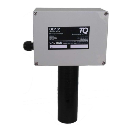
J-Box With Amplifier. The junction box provides resistance to physical shock and gas-free protection to the components mounted inside. The J-box contains a cover and provision for both a cable gland at the cable entry point (16mm conduit thread) and a separate earthing point. The amplifier printed circuit board(s) (PCB) installed inside the J-Box, contains an amplifier circuit for converting the IR detector’s absorption signals into a 4-20mA output signal and, when required, relays to provide volt-free alarm contacts. -
Page 7: Performance Specification
PERFORMANCE SPECIFICATIONS. Table 1. GD131 Sensor Performance Specifications. FACTOR SPECIFICATION Detection Method: IR Absorption Sampling Method: Continuous Diffusion Measuring Range: 0 – 2000 ppm R134a. Other gases may have different ranges. Higher ranges are available Versions: 1) 4-20mA output (TQ P/N 131-020 & 131-021) 2) 2 x “change-over”... -
Page 8: Installation
INSTALLATION MECHANICAL INSTALLATION. 2.1.1 GENERAL. The GD131 Sensor is designed to be installed with the optical bench pointing down (ie below the junction box). Figure 1 shows the installation Mounting Mounting Holes Holes Gas Entry Junction Points (Diffusion Version) Optical Bench Guard Tube Notes:... -
Page 9: Installation Guidelines
2.1.2 INSTALLATION GUIDELINES. To ensure continued reliable operation of the GD131 Sensor, the following installation guidelines should be observed: CAUTION The calibration of the sensor may be affected by exposure to direct sunlight. If it is necessary to install the sensor unit in a sunlit area, provide an adequate sunshade for the sensor unit. ... -
Page 10: Electrical Installation
ELECTRICAL INSTALLATION. 2.2.1 4-20mA Version The amplifier circuit in the PCB supplies a 4-20mA output signal, which is a current source only. An external common ground return must be provided, as shown in Figure 2. Total circuit load and cable resistance should be less than 600 Ohms for the 4-20mA loop. The +24Vdc and common ground leads must be of sufficiently low resistance to ensure the correct operating voltage at the PCB . -
Page 11: Commissioning & Calibration
COMMISSIONING & CALIBRATION COMMISSIONING. Prior to connecting power to the GD131 Sensor, the following preliminary checks should be made. Ensure the GD131 is securely mounted and inspect the unit for signs of damage or corrosion to the sensor assembly or its junction box/enclosure. CAUTION. - Page 12 Reset baseline using onboard pcb button. Before starting the adjustment procedure it is necessary to remove the lid form the enclosure (4 screws) and locate the calibration button on the main pcb. See Figure 5 Calibration Calibration Button Power & 4-20mA Connector Power Indicator...
-
Page 13: Output Current Calculation
Reset baseline using Calibration Magnet. On some sensors, the pcb reset button is not fitter. These sensors have a “Red Dot” calibration mark on the case. See Figure 6 and can be adjusted using the supplied calibration magnet. Figure 6. Calibration using a Magnet The procedure is exactly the same as if using the onboard pcb button. -
Page 14: Maintenance
The sensor output indicates a fault condition (<4mA), or The sensor does not respond to the gas. In each case refer the unit to TQ Environmental Limited for service. CAUTION THE OPTICAL BENCH AND THE SENSOR AMPLIFIER CIRCUITS ARE MATCHED TO EACH OTHER AT THE FACTORY AND NEITHER SHOULD BE REPLACED AS A SINGLE UNIT. - Page 15 Issue:8 March 2020 4951MMA8 page 15 of 16...
- Page 16 TQ Environmental Limited, Silkwood Court, Wakefield, West Yorkshire, WF5 9TP. United Kingdom Tel: +44 (0) 1924 271013 Email: sales@tqenv.com Fax: +44 (0) 1924 264420 Web: www.tqenv.com Issue:8 March 2020 4951MMA8 Page 16 of 16...
Need help?
Do you have a question about the TQ131 and is the answer not in the manual?
Questions and answers