Table of Contents
Advertisement
Quick Links
TQ Environmental Ltd
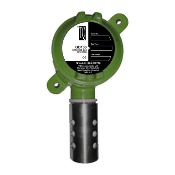
GD133 INFRARED
GAS SENSOR
OPERATING MANUAL
© TQ Environmental Ltd 2017
This manual must not be copied or reproduced in part without the express written
permission of TQ Environmental Ltd. All information contained herein is subject to
modification.
TQ Environmental Ltd, Silkwood Court, Wakefield, West Yorkshire, WF5 9TP
44 (0) 1924 271013 FAX 44 (0) 1924 264420
TQ ENVIRONMENTAL LTD BS EN ISO 9001
Filename: 5832T4
Page 1 of 14
Advertisement
Table of Contents

Related Manuals for TQ Environmental GD133


Summary of Contents for TQ Environmental GD133
- Page 1 © TQ Environmental Ltd 2017 This manual must not be copied or reproduced in part without the express written permission of TQ Environmental Ltd. All information contained herein is subject to modification. TQ Environmental Ltd, Silkwood Court, Wakefield, West Yorkshire, WF5 9TP ...
-
Page 2: Table Of Contents
TQ Environmental Ltd CONTENTS: Page no: Proprietary Warning, Cautions and Notes Safety Warnings Section 1 Description 1.1 General description 1.2 Method of detection 1.3 Sensor unit 1.4 Performance specifications Section 2 Installation 2.1 Mechanical installation 2.2 Electrical installation Section 3 Commissioning and Calibration 3.1 Commissioning... -
Page 3: Proprietary
While great efforts have been made to assure the accuracy and clarity of this document, TQ Environmental LTD assumes no liability resulting from any omissions in this document, or from misuse of the information obtained herein. The information in this document has been carefully checked and is believed to be entirely reliable with all of the necessary information included. -
Page 4: Safety Warnings
TQ Environmental Ltd SAFETY WARNINGS THE GD133 INFRA RED GAS SENSOR SHOULD ONLY BE OPERATED IN AN ENVIRONMENT WHICH IS NON-HAZARDOUS. THE GD133 IS NOT CERTIFIED FOR USE IN ANY HAZARDOUS AREA. FOR SAFETY REASONS, THE GD133 INFRA-RED GAS SENSOR MUST BE INSTALLED, OPERATED AND SERVICED BY QUALIFIED PERSONNEL ONLY. -
Page 5: General Description
SECTION 1 - DESCRIPTION GENERAL DESCRIPTION The GD133 Infra-Red Gas Sensor is a highly reliable infra-red (IR) absorption type sensor designed to give extended service under extreme conditions. The sensor is used to detect the presence of infra-red active gases, eg carbon dioxide. In a typical... - Page 6 TQ Environmental Ltd J-BOX WITH AMPIFIER INSIDE 81.3 STANDARD CO NFIGURATIO N M20 THREAD 88 Approx 81.3 220 APPROX M25 x 1.5mm THREAD WEATHER PROTECTION SHIELD SIDE VIEW PLAN VIEW Figure 1 - Configuration J-Box With Amplifier. The junction box provides resistance to physical shock and gas-free protection to the components mounted inside.
- Page 7 TQ Environmental Ltd Flame Arrestor. The Flame Arrestor is made of 316 Sintered Stainless Steel. The stainless steel ensures high corrosion-resistance. The arrestor has a sheet of filter material fixed around the outside to stop the entrance of dust, dirt and moisture.
-
Page 8: Performance Specifications
TQ Environmental Ltd PERFORMANCE SPECIFICATIONS. Table 1. GD133 Sensor Performance Specifications. FACTOR SPECIFICATION Detection Method: IR Absorption Sampling Method: Continuous Diffusion 0 – 2% volume. (The actual gas and range is displayed Measuring Range for CO2: on the label). Accuracy:... -
Page 9: Mechanical Installation
MECHANICAL INSTALLATION. 2.1.1 GENERAL. The GD133 Sensor is designed to be installed with the junction box and Flame Arrestor Assembly with the Guard pointing downward. A typical installation for the GD133 Sensor is shown in Figure 3. Figure 3. Sensor Unit Installation and Orientation. -
Page 10: Electrical Installation
Liquid Teflon, to the gland threads and install the appropriate sealing washers. When the GD133 is used in conjunction with a calibration cup for checking operation the junction box must be mounted at least 10mm away from a vertical surface. -
Page 11: Commissioning
It is likely that the GD133 Sensor will remain stable at its initial calibration settings for long periods (typically 3 years) and on-site calibration is NOT required. Please refer to 4.1 (Routine Maintenance) for details of how to check the output from the sensor. -
Page 12: 3.3 Output Current Fault Conditions
TQ Environmental Ltd 3.3 OUTPUT CURRENT FAULT CONDITIONS. The GD133 provides differing current output levels between 0mA and 4mA to indicate various sensor fault conditions. Indicated Current Description Output 0.5mA Warm up after application of power to the unit until the GD133 has completed its self-testing. -
Page 13: Routine Maintenance
In this case, any small adjustment of the output can be corrected on the control system receiving the signal from the GD133. Please refer to the documentation associated with the control system for details on how to carry out any adjustment which is necessary. -
Page 14: Spares
TQ Environmental Ltd Filename: 5832T4 Page 14 of 14...
Need help?
Do you have a question about the GD133 and is the answer not in the manual?
Questions and answers