Advertisement
Quick Links
INSTALLATION AND MAINTENANCE INSTRUCTIONS
OSY2 Gate Valve
Supervisory Switch
Specifications
Contact Ratings:
Dimensions:
Maximum Stem Extension:
Minimum Stem Extension:
Bracket Span:
Operating Temperature Range:
Shipping Weight:
Enclosure Rating:
U.S. Patent Number:
Important
Please Read Carefully And Save
This instruction manual contains important information
on the installation and operation of supervisory switches.
Purchasers who install supervisory switches for use by oth-
ers must leave this manual or a copy of it with the user.
These instructions apply to Safe Signal switches for out-
side screw and yoke valves only. Read all instructions
carefully before beginning installation.
Do NOT use this switch in explosive or potentially explosive
atmospheres.
Do NOT leave unused wires exposed.
All supervisory switch installations must comply with local codes
and ordinances and the requirements of the authority having
jurisdiction. Additional information is available in National Fire
Protection Association standards NFPA 13, 13D, 13R, 71, and 72.
General Installation Considerations
The OSY2 Supervisory Switch can be mounted on open yoke
valves between
1
⁄
" and 12" in diameter in the positions shown
2
in Figure 1 only. If the switch is installed with the actuator
pointing upward, water may leak into the interior of the switch.
Therefore, do NOT install the OSY2 with its actuating lever
pointing upward.
All OSY2 models are equipped with a ground screw inside the
switch housing near the conduit exit hole for those applications
where grounding is required.
10 A @ 125/250 VAC
2.5 A @ 24 VDC
5
3
⁄
"H X 3
1
⁄
"W X 3
4
2
2
⁄
"
5
8
"
5
⁄
8
6
3
⁄
"
4
32° – 120°F (0°C – 49°C)
2
3
⁄
lb.
4
NEMA Type 3R when mounted with the actuator vertical (cover on top) as tested by
Underwriters Laboratories, Inc.
IP54
5,213,205
WARNING
1
⁄
"L
4
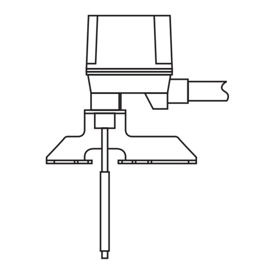
THE FOLLOWING ARE EXAMPLES OF
ACCEPTABLE MOUNTING POSITIONS:
Figure 1:
ACTUATOR
VERTICAL (DOWN)
Narrow Yoke Valves
As Figure 2 suggests, installing the valve with mounting bolts
inside the yoke is recommended. However, some valves may have
yokes that are too narrow for this arrangement. If this is the case,
the bolts can be positioned on the outside of the yoke.
Limited Clearance Valves
The OSY2 mounting bracket fits most of the open yoke valves
used in fire protection systems. However, some of these valves,
especially those less than 1
shaped yokes or such limited clearances that the clamping bar
cannot be installed properly and/or it causes the valve to bind. If
this is the case, the use of J-bolts is required to attach the OSY2
to the valve (see J-Bolt Detail, Figure 2). J-bolts can be purchased
separately by ordering the OSYRK Replacement Kit.
Installation Instructions
See Figures 2 and 3, as required, while performing the procedure
that follows.
Perform step 1 on valves 1
Proceed directly to step 2 if the switch is being installed on a
valve larger than 1
1
ACTUATOR
HORIZONTAL
" in diameter, have irregularly
1
⁄
2
1
⁄
" in diameter and smaller only.
2
1
⁄
" in diameter.
2
THE FOLLOWIN
POSITION IS N
ACTUAT
(POI
W0221-00
I56-0393-J
4/21
Advertisement

Related Manuals for Safe Signal OSY2


Summary of Contents for Safe Signal OSY2
- Page 1 ⁄ ″ and 12″ in diameter in the positions shown this is the case, the use of J-bolts is required to attach the OSY2 in Figure 1 only. If the switch is installed with the actuator to the valve (see J-Bolt Detail, Figure 2). J-bolts can be purchased pointing upward, water may leak into the interior of the switch.
- Page 2 Figure 2: W0222-00 J-Bolt Detail W0207-00 I56-0393-J 4/21...
- Page 3 The switch closure can also be tested electri- 2. Set the valve to its fully open position. Remove the OSY2 cally by using an ohmmeter to test for continuity between its Supervisory Switch from the carton and adjust the position of terminals.
- Page 4 SAFE SIGNAL for inspection. Upon a determination by SAFE SIGNAL defective manufacture, labeling, or packaging. that a product is not as warranted, SAFE SIGNAL shall, at its exclusive option, replace or repair said defective product or parts thereof at its own expense except that Purchaser shall pay all...
Need help?
Do you have a question about the OSY2 and is the answer not in the manual?
Questions and answers