Advertisement
Installation AND MAINTENANCE INSTRUCTIONS
EPS40EXP and EPS120EXP Explosion Proof
Supervisory Pressure Switches
Specifications
Contact Ratings:
Operating Temperature Range:
Maximum Service Pressure (in PSI):
Adjustment Range:
Approximate Differential:
Enclosure Rating:
Hazardous Atmospheres
Classification:
Important
Please Read Carefully and Save
This instruction manual contains important information about
the installation and operation of supervisory pressure switches.
Purchasers who install switches for use by others must leave this
manual or a copy of it with the user.
Read all instructions carefully before installation, following only
those instructions that apply to the model you are installing.
Before installing any alarm device, be thoroughly familiar with:
NFPA 72:
National Fire Alarm Code
NFPA 13:
Installation of Sprinkler Systems
NFPA 25:
Inspection, Testing, and Maintenance of Water-
based Fire Protection Systems
Other applicable NFPA standards, local codes, and the require-
ments of the authority having jurisdiction.
Failure to follow these directions may result in failure of the
device to report an alarm condition. Safe Signal is not respon-
sible for devices that have been improperly installed, tested, or
maintained.
10 A, 1/2 HP @ 125/250 VAC
2.5A @ 6/12/24 VDC
–40°F to +160°F
EPS40EXP
EPS120EXP
250
250
10-100
10-200
3 PSI @ 10 PSI
3 PSI @ 10 PSI
8 PSI @ 100 PSI
9 PSI @ 200 PSI
NEMA Type 4 — Indoor/Outdoor use
Class I, Groups B, C, D, Div. 1
Class II, Groups E, F, G, Div. 1
Class III, Div. 1
Operation
As pressure changes, a diaphragm actuates 2 snap action switch-
es. The pressure switch actuation is determined by adjustment
settings.
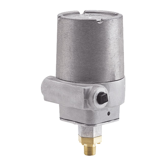
Figure 1. Pressure switch basic dimensions:
1
4.9"
COVER
LOCKING
SCREW
HEX ADJUST
SCREW
1/4" HEX HEAD
COVER
TAM PER
SET SCREW
(WRENCH
PROVIDED)
ADJUSTMENT
WHEEL
9.5"
COVER
(WRENCH
PROVIDED)
MAIN ADJUSTMENT
WHEEL (TURN
COUNTERCLOSKWISE
TO INCREASE
PRESSURE)
1/2" NPT
W0174-00
I56-1428-C
4/21
Advertisement
Table of Contents

Related Manuals for Safe Signal EPS40EXP


Summary of Contents for Safe Signal EPS40EXP
- Page 1 9.5" Failure to follow these directions may result in failure of the COVER (WRENCH PROVIDED) device to report an alarm condition. Safe Signal is not respon- sible for devices that have been improperly installed, tested, or maintained. MAIN ADJUSTMENT LOCKING...
- Page 2 Figure 2. Typical piping diagram for EPS40EXP Figure 3. Typical piping diagram for EPS120EXP WIRE TO ALARM WIRE TO SUPERVISORY CIRCUIT OF FIRE ALARM INDICATING CIRCUI EPS120EXP PRESSURE CONTROL PANEL OF FIRE ALARM EPS40EXP EPS10EXP CONTROL PANEL SUPPLY SPRINKLER SYSTEM...
- Page 3 SAFE SIGNAL for inspection. Upon a determination by SAFE SIGNAL defective manufacture, labeling, or packaging. that a product is not as warranted, SAFE SIGNAL shall, at its exclusive option, replace or repair said defective product or parts thereof at its own expense except that Purchaser shall pay all...
Need help?
Do you have a question about the EPS40EXP and is the answer not in the manual?
Questions and answers