Table of Contents
Advertisement
Quick Links
Z4 Installation Guide
About this Guide
This guide provides instructions on how to install and configure your Z4 series device. This guide also provides
mounting instructions and limited troubleshooting procedures. For more Z-series device installation guides, refer to the
Z-series
installation guides section
Product Overview
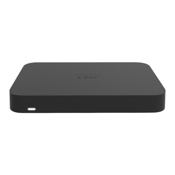
The Cisco Meraki Z-Series teleworker gateway is an enterprise class firewall, VPN gateway and router. Each model
offers wireless connectivity, five gigabit ethernet ports, including a built-in PoE-enabled port for VoIP phones and other
powered devices. Each model is designed to securely extend the power of Meraki cloud managed networking to almost
any location.
Features
• Managed via Cisco Meraki Dashboard
• Automatic Firmware upgrades
• Automatic WAN Failover to Cellular Uplink
• L3/L7 Stateful Firewall
• 1:1 and 1:Many NAT
• Configurable VLANs / DHCP support
on our documentation website.
1
Advertisement
Table of Contents

Related Manuals for Cisco MERAKI Z4


Summary of Contents for Cisco MERAKI Z4
- Page 1 Z4 Installation Guide About this Guide This guide provides instructions on how to install and configure your Z4 series device. This guide also provides mounting instructions and limited troubleshooting procedures. For more Z-series device installation guides, refer to the Z-series installation guides section on our documentation website.
- Page 2 • Static Routing • Client VPN endpoint • Meraki AutoVPN and L2TP/IPSec VPN endpoint • Custom Traffic Shaping • Historical Client Usage statistics • Netflow support • Syslog integration • Remote Packet Capture tools • IPv6 Support Context and Comparisons Max Stateful Firewall 500 Mbps Throughput in NAT mode...
-
Page 3: Physical Specifications
Physical Specifications RJ45 WAN Interfaces 1x Dedicated GbE RJ45 LAN Interfaces - Dedicated 4x Dedicated GbE RJ45 Wireless Radio Information WiFi 6 2x2 MU-MIMO Antennas 2 x 2 MU-MIMO with two spatial streams Maximum Wireless Data Rate 1.5 Gbps* Mount Type Desktop / Wall Mount Dimensions 7.25 x 4.84 x 1.10 in /... - Page 4 1x AC Power Cable, US plug MA-PWR-CORD-EU 1x AC Power Cable, EU plug MA-PWR-CORD-UK 1x AC Power Cable, UK plug MA-PWR-CORD-AU 1x AC Power Cable, AU plug Product View and Physical Features Package Contents In addition to the Z4 device, the following are provided:...
- Page 5 Power Adapter (No Power Cable) 1x CAT5e Ethernet Cables Wall Screws and Anchors Front Panel Status Indicator LED Status Meaning Power is applied but the appliance is not Solid orange connected to the Meraki Dashboard The appliance is attempting to connect to Meraki Rainbow Colors Dashboard...
- Page 6 Flashing White Firmware upgrade in progress Fully operational/connected, uplink actively Solid White using wired WAN Back Panel Additional functions on the back panel are described below, from left to right. Insert a paper clip if a reset is required. • Press for 1 second to delete a downloaded configuration and reboot.
-
Page 7: Bottom Panel
A steady green LED indicates bidirectional connectivity, and flashing green indicates traffic. Designed for use only with the unit’s power Power input supply. Bottom Panel Please note that the serial number is located on the product label on the bottom panel of the Z4... -
Page 8: Mounting Hardware
You should complete the following steps before going on-site to perform an installation. Configure your Dashboard Network The following is a brief overview only of the steps required to add an Z4 to your network. For detailed instructions about creating, configuring and managing Meraki networks, refer to our Managing Dashboard Networks document. -
Page 9: Installation Instructions
4. Go to the map / floor plan view and place each Z4 on the map by clicking and dragging it to the location where you plan to mount it. -
Page 10: Connecting To Wan
Connecting to WAN All Meraki Z4 devices must have an IP address. This section describes how to configure your local area network before you deploy it. A local management web service, running on the appliance, is accessed through a browser running on a client PC. -
Page 11: Additional Settings
Setting up a DHCP IP Address By default all Z4 devices are configured to DHCP from upstream WAN / ISP servers. Simply plug the Z4’s WAN / Internet port to your upstream circuit and wait a few minutes for the unit to negotiate a DHCP address. -
Page 12: Basic Troubleshooting
Web Proxy Settings These settings take effect if the Z4 device has to fall back to using HTTP to contact the Cloud Controller. By default, web proxy is disabled. To enable web proxy, do the following: • Choose Web proxy > Yes. - Page 13 Meraki Z4 devices have been tested and found to comply with the limits for a Class B digital device, pursuant to part 15 of the FCC rules. These limits are designed to provide reasonable protection against harmful interference in a residential installation.
- Page 14 specified in the operational documentation and/or on the equipment labeling. • The equipment is not for domestic use. The equipment is intended for operation without the constant presence of maintenance personnel. • The equipment is subject to installation and maintenance by specialists with the appropriate qualifications, sufficient specialized knowledge, and skills.
Need help?
Do you have a question about the Z4 and is the answer not in the manual?
Questions and answers