Ekinex EK-ET2-TP, EK-ET2-TP-P - Room Temperature Controller Manual
- Quick start manual (8 pages)
Advertisement
- 1 Description
- 2 Main functional characteristics
- 3 Technical data
- 4 Accessories
- 5 Mounting
- 6 Mounting position
- 7 Switching, display and measuring elements
- 8 Connection of the KNX bus line
- 9 Configuration and commissioning
- 10 Marks
- 11 Maintenance
- 12 Disposal
- 13 Warnings
- 14 Other information
- 15 Documents / Resources
Description
Room temperature controller with humidity and CO 2 equivalent regulator.
Codes:
EK-ET2-TP (for round and square wall box)
EK-ET2-TP-R (for rectangular wall box)

The ekinex® EK-ET2-TP... room temperature controller is a KNX S-mode device for the independent temperature regulation of a room or a zone in a building. It can be installed in houses and buildings (e.g., offices, hotels, private house, etc.).
The room temperature controller is equipped with 3 sensors: temperature, relative humidity and air quality (as CO2 equivalent). It can also work as a controller for these 3 parameters, that are available for a single zone to be managed. Up to 8 LEDs can be configured, in order to display the operating thresholds for the CO2 equivalent, the activation of the humidification/dehumidification functionality and the cooling/heating working modes. The device is equipped with an integrated KNX bus communication module and is designed for wall installation on a flush mounting box. Both the programming button and LED are located in the front of the device below the rocker, as well as the 3 sensors.
The device is powered by the KNX bus line and does not require any auxiliary power supply.
Main functional characteristics
The common features to all versions are documented as follows:
- Temperature, relative humidity and air quality (CO equivalent) measuring through the integrated sensors, with possibility of sending the read valued on the bus;
- Two-point (ON/OFF) or proportional (PWM or continuous) room temperature regulation;
- Seasonal modes: heating and cooling with possibility of either local or via bus seasonal changeover;
- Operating modes: comfort, standby, economy and building protection with different setpoint for heating and cooling functions;
- Automatic switching of the operating modes through presence sensor or window contact;
- Weighted average of two temperature values;
- Dew-point temperature computation;
- Temperature regulation (measured and setpoint, as °C), relative humidity (measured and setpoint in percentage), air quality (as CO2 equivalent concentration, in ppm), alarms and errors (with alphanumeric coding);
- Relative humidity thresholds setting;
- CO2 equivalent thresholds setting;
- Floor temperature limitation and antincondensation (for radiant panels);
- Delayed start of a fan ("hot-start") with time-scheduling or depending on the water temperature measured at the coil for thermal exchange.
Other characteristics
- Plastic casing for wall mounting
- Integrated temperature, relative humidity and air quality (CO2 equivalent) sensors
- Protection degree IP20 (according to EN 60529)
- Classification climatic 3K5 and mechanical 3M2 (according to EN 50491-2)
- Pollution degree 2 (according to IEC 60664-1)
Technical data
- 30 Vdc power supply through KNX bus
- Current consumption from bus < 13 mA
Environmental conditions
- Operating temperature: - 5... + 45°C
- Storage temperature: - 25... + 55°C
- Transport temperature: - 25... + 70°C
- Relative humidity: 95% not condensing
Accessories
A metallic support, the fixing screws and the terminal for connection of the KNX bus line are delivered with the device. This has to be completed with the following items:
- a square rocker 60 x 60 mm, with set code EKT1Q-..., to be filled with the specific colour and material extension;
- a single plate and a frame, to be ordered separately, except for the 'NF (No Frame) version, which do not require any frame.
Plate
The device has to be completed with an ekinex® single plate with 60 x 60 mm window (EK-PQS-...) in combination with an adapter for mounting with frame of the Form or Flank series or without frame. It is also possible the double mounting with 71 mm center-to-center distance in combination with double plates that must have (at least) one 60 x 60 mm window (EK-P2G-... or EK-P2S-...).
Single square plate

with one 60 x 60 mm window Code EK-PQS-... (to be used with EK-ET2-TP)
Single rectangular plate

with one 60 x 60 mm window Code EK-PRS-... (to be used with EK-ET2-TP-R)
Double plate

with one 60 x 60 mm window
and one 55 x 55 mm window
Code EK-P2G-...
Double plate

with two 60 x 60 mm windows
Code EK-P2S-...
 Note. Frame and rockers for the completion of the device have to be ordered separately. For further information about materials, colours and finishing available see also the ekinex® product catalog or browse www.ekinex.com.
Mounting
The device has degree of protection IP20, and is therefore suitable for use in dry interior rooms. The installation of the device requires the following steps.
Mounting with frame
- fix the metallic support (h) with the screws (g) on a flush-mounting box (i) provided with suitable fixing holes;
- snap a square frame (f) of the form or flank series, inserting it from the rear of the preassembled thermostat-adapter (d+e);
- insert the bus terminal, previously connected to the bus cable, in its slot on the rear side (see also: "Connection of the KNX bus line"). At this point it is recommended to carry out the commissioning of the pushbutton (see also "Configuration and commissioning") or at least the physical address download;
- insert thermostat and adapter (d+e), completed with the frame (f), in the metallic support (h). Mounting the pushbutton follow the indication TOP (arrow tip pointing up) on the rear side of the device;
- tighten thermostat, adapter and frame (d+e+f) on the metallic support (h) with the two screws (c);
- snap the plate (a);
- snap the rocker (b) to complete the installation.

- 1-fold plate
- Rocker
- Screws (for device)
- Device
- Adapter (delivered preassembled on the device)
- Frame (square, form or flank series)
- Screws (for metallic support)
- Metallic support
- Flush-mounting box (not delivered by SBS)
Mounting with frame ('NF series)
Carry out the following steps:
- insert the metallic support (f) on the adapter (g);
- fix adapter and metallic support (f+g) with the screws (e) on a flush-mounting box (h) provided with suitable fixing holes;
- insert the bus terminal, previously connected to the bus cable, in its slot on the rear side (see also: "Connection of the KNX bus line"). At this point it is recommended to carry out the commissioning of the pushbutton (see also "Configuration and commissioning") or at least the physical address download;
- insert the thermostat (d) in the support-adapter (f+g). Mounting the device follow the indication TOP (arrow tip pointing up) on the rear side of the device;
- tighten the device on the support-adapter (f+g) with the two screws (c);
- snap the plate (a);
- snap the rocker (b) to complete the installation.
")
- 1-fold plate
- Rocker
- Screws (for device)
- Device
- Screws (for metallic support)
- Metallic support
- Adapter for 'NF series (delivered with the device)
- Flush-mounting box (not delivered by SBS)
Mounting with rectangular flush-mounting box
Carry out the following steps:
- insert the metallic support (f) on the adapter (g);
- for versions provided with frame only: snap a rectangulare frame (f) of either form or flank series, starting from the back side of the support-adapter group (f+g);
- fix adapter and metallic support (f+g) (and eventually the frame, h) with the screws (e) on a flush-mounting box (i) provided with suitable fixing holes;
- insert the bus terminal, previously connected to the bus cable, in its slot on the rear side (see also: "Connection of the KNX bus line"). At this point it is recommended to carry out the commissioning of the pushbutton (see also "Configuration and commissioning") or at least the physical address download;
- insert the thermostat (d) in the support-adapter (f+g). Mounting the device follow the indication TOP (arrow tip pointing up) on the rear side of the device;
- tighten the device on the support-adapter (f+g) with the two screws (c);
- snap the plate (a);
- snap the rocker (b) to complete the installation.

- 1-fold plate (square, with 60 x 60 mm window)
- Rocker
- Screws (for device)
- Device
- Screws (for metallic support)
- Metallic support
- Plastic adapter
- Rectangular frame (not for NF version)
- Flush-mounting box (not delivered by SBS)
Mounting position
For optimum regulation the device has to be preferably installed on an internal wall at the height of 1.5 m and at least 0.3 m far from doors. The device cannot be installed close to heat sources such as radiators or domestic appliances or in positions subject to direct sunlight. If necessary, for the regulation may be used a weighted average between two values selected among the following ones: value measured by the internal sensor, value measured by a temperature sensor connected to a device input, value received via bus by another KNX device (e.g. from ekinex pushbuttons).

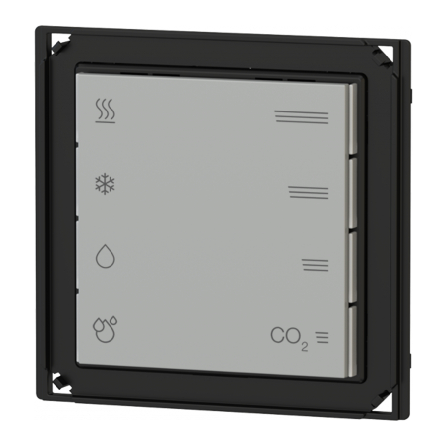
Switching, display and measuring elements
The device is equipped with a programming LED, 8 displaying LEDs with lightguides for feedback status and 3 sensors.
Switching elements
- Pushbutton (12) for switching between the normal and programming operating mode.
Display elements
- Red LED (4) for indication of the heating mode functionality ON;
- Blue LED (5) for indication of the cooling mode functionality ON;
- White LED (6) for indication of the dehumidification functionality ON;
- Green LED (7) for indication of the humidification functionality ON;
- Red LED (8) for indication that the measured CO equivalent exceeds threshold 3;
- White LED (9) for indication that the measured CO equivalent lies between threshold 2 and 3;
- Blue LED (10) for indication that the measured CO equivalent lies between threshold 1 and 2;
- Green LED (11) for indication that the measured CO equivalent lies below threshold 1;
- Red LED (12) for indication of the active operating mode (on = programming, off = normal operation).
For measuring purposes the device is provided with:
- a temperature sensor (located behind passage 15);
- a relative humidity sensor (14);
- a CO2 equivalent air quality sensor (16).

- Terminal block for KNX bus line
- Product label
- Adapter
- Red LED (heating ON)
- Blue LED (cooling ON)
- Blue LED (dehumidification ON)
- Green LED (humidification ON)
- Red LED (CO2 equivalent concentration > threshold 3)
- Blue LED (CO2 eq. concentration between threshold 2 and 3)
- Blue LED (CO2 eq. concentration between threshold 1 and 2)
- Blue LED (CO2 equivalent concentration < threshold 1)
- Programming LED
- Programming pushbutton
- Relative humidity sensor
- Temperature sensor
- CO2 equivalent sensor
Note. Programming pushbutton and LED are accessible from the front side of the device. The device addressing may be easily carried out after the assembly of the frame, removing the rockers. Once the addressing has been done, the device configuration can be later downloaded without pressing the programming pushbutton.
Connection of the KNX bus line
The connection of the KNX bus line is made with the terminal block (red / black) included in delivery and inserted into the slot of the casing.
Characteristics of the KNX terminal block
- spring clamping of conductors
- 4 seats for conductors for each polarity
- terminal suitable for KNX bus cable with single-wire conductors and diameter between 0.6 and 0.8 mm
- recommended wire stripping approx. 5 mm
- color codification: red = + (positive) bus conductor, black = − (negative) bus conductor

In order to supply the KNX bus lines use only KNX bus power supplies (e.g. ekinex EK-AB1TP or EK-AG1-TP). The use of other power supplies can compromise the communication and damage the devices connected to the bus.

The electrical connection of the device can be carried out only by qualified personnel. The incorrect installation may result in electric shock or fire. Before making the electrical connections, make sure the power supply has been turned off.
Configuration and commissioning
Configuration and commissioning of the device require the use of the ETS® (Engineering Tool Software) program V4 or later releases. These activities must be carried out according to the design of the building automation system done by a qualified planner.
Note. The configuration and commissioning of KNX devices require specialized skills. To acquire these skills, you should attend the workshops at KNX certified training centers.
Configuration
For the configuration of the device parameters the corresponding application program or the whole ekinex® product database must be loaded in the ETS program. For detailed information on configuration options, refer to the application manual of the device available on the website www.ekinex.com.
| Product code | Application software (## = release) | Communication objects (max nr.) | Group adresses (max nr.) |
| EK-ET2-TP | APEKET2TP##.knxprod | 137 | 254 |
Commissioning
For commissioning the device the following activities are required:
- make the electrical connections as described above;
- turn on the bus power supply;
- switch the device operation to the programming mode by pressing the programming pushbutton located on the front side of the housing. In this mode of operation, the programming LED is turned on;
- download into the device the physical address and the configuration with the ETS ® program.
At the end of the download the operation of the device automatically returns to normal mode; in this mode the programming LED is turned off. Now the bus device is programmed and ready for use.
Marks
- KNX
- CE: the device complies with the Low Voltage Directive (2014 / 35 / EU) and the Electromagnetic Compatibility Directive (2014 / 30 / EU). Tests carried out according to EN 50491-5-1:2010 and EN 50491-52:2010
Maintenance
The device is maintenance-free. To clean it use a dry cloth. It must be avoided the use of solvents or other aggressive substances.
Disposal

At the end of its useful life the product described in this datasheet is classified as waste from electronic equipment in accordance with the European Directive 2012 / 19 / EU (WEEE recast), and cannot be disposed together with the municipal undifferentiated solid waste.
Incorrect disposal of this product may cause serious damage to the environment and human health. Please be informed about the correct disposal procedures for waste collecting and processing provided by local authorities.
Warnings
- Installation, electrical connection, configuration and commissioning of the device can only be carried out by qualified personnel in compliance with theapplicable technical standards and laws of the respective countries
- Opening the housing of the device causes the immediate end of the warranty period
- In case of tampering, the compliance with the essential requirements of the applicable EU directives, for which the device has been certified, is no longer guaranteed
- ekinex ® KNX defective devices must be returned to the manufacturer at the following address: SBS S.p. A. Via Novara 35, I-28010 Vaprio d'Agogna (NO) Italy
Other information
- The instruction sheet must be delivered to the end customer with the project documentation
- For further information on the product, please contact the ekinex ® technical support at the e-mail address: support@ekinex.com or visit the website www.ekinex.com
- Each ekinex ® device has a unique serial number on the label. The serial number can be used by installers or system integrators for documentation purposes and has to be added in each communication addressed to the SBS technical support in case of malfunctioning of the device
- ekinex ® is a registered trademark of SBS S.p. A.
- KNX ® and ETS ® are registered trademarks of KNX Association cvba, Brussels
© SBS S.p. A. 2017. The company reserves the right to make changes to this documentation without notice.
Versions
| Code | Finishing | Wall box |
| EK-E12-TP | with frame or no-frame (flank or form series) | round (distance between holes 60 mm) |
| EK-E12-TP-R | with frame or no-frame (flank or form series) | rectangular (distance between holes 83,5 mm) |

Direct access to documentation
The QR code allows the direct access to the technical documentation using mobile devices (smart phones, tablets) with a standard QR code reader.
 is a registered brand of
SBS S.p. A.
HQ
Via Circonvallazione s/n
I-28010 Miasino (NO) Italy
Tel. +39 0322 980909
Fax +39 0322 980910
R&D
Via Novara 35
I-28010 Vaprio d'Agogna (NO) Italy
Tel. +39 0321 966740/1 Fax +39 0321 966997
info@ekinex.com
www.ekinex.com

Documents / Resources
References
Download manual
Here you can download full pdf version of manual, it may contain additional safety instructions, warranty information, FCC rules, etc.
Download Ekinex EK-ET2-TP, EK-ET2-TP-P - Room Temperature Controller Manual
Advertisement


Need help?
Do you have a question about the EK-ET2-TP and is the answer not in the manual?
Questions and answers