Advertisement
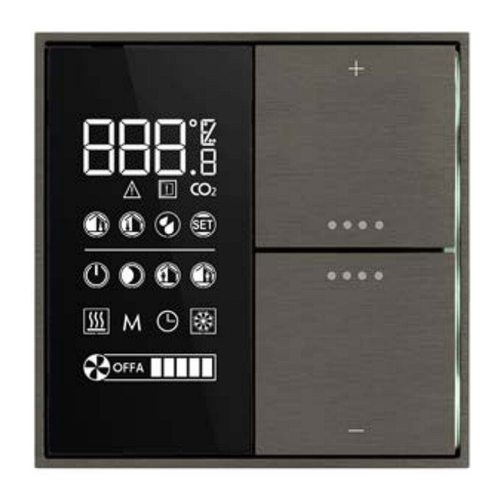
Room temperature controller
with LC-display
Codes: EK-EP2-TP-...
EK-EQ2-TP-... (with R.H. sensor)
S
TP1
KNX thermostat with LC-display for the independent ther-
mal regulation of a room or a zone. It has to be used in
KNX installations for control of homes and buildings.
Description
The ekinex
room temperature controller is a KNX S-mo-
®
de device for the independent temperature regulation of
a room or a zone in a building. In combination with one
or more KNX actuators, the room temperature controller
is able to control the heating and cooling emission of a
series of terminal units for the thermal exchange (such
as radiators, fan-coils, floor and ceiling radiant panels,
etc.). The device is provided with a LC-display with adju-
stable backlight, a sensor for temperature measuring and
two freely configurable inputs for the connection of e.g.
window contacts or temperature sensors. The device is
equipped with an integrated KNX bus communication
module and is designed for wall installation on a flush
mounting box. For controlling the room temperature con-
troller functions the integrated 2-fold pushbutton is used.
It is provided with four LED for each channel programma-
ble e.g. as status feedback or orientation nightlight. The
device is powered by the KNX bus line and does not re-
quire any auxiliary power supply.
EK-EQ2-... versions
The EK-EQ2-... versions are provided with a relative hu-
midity sensor and additional functions that use the physi-
cal value measured by the sensor.
Versions and accessories
The device has to be completed with a set of 2 square ro-
ckers specific for the room temperature controller; depen-
ding on the version, a square frame of the form or flank
series may be necessary. A metallic support, the fixing
screws and the terminal for connection of the KNX bus
line are delivered with the device.
Datasheet STEKEQ2TP_IT
Main functional characteristics
The characteristics common to all versions are:
• Temperature measuring through integrated sensor with
• 2-point (on/off) or proportional (PWM or continuous)
• Ventilation control with continuous or 3-speed regula-
• Seasonal modes: heating and cooling with possibility of
• Operating modes: comfort, standby, economy and bu-
• Manual or automatic control of fan-coil units with 2 or
• Automatic switching of the operating modes depending
• Weighted average of two temperature values
• Temperature displaying (measured, setpoint and
• Floor temperature limitation and antincondensation (for
• Antistratification function
• Automatic switching between operating modes through
• Delayed start of a fan ("hot-start") with time-scheduling
• Window opening reporting
The EK-EQ2-... versions offer additional functions for:
• Relative humidity measuring through the integrated
• Humidification and dehumidification control
• Sending on the bus of the condition internal or external
• Calculation of psychrometric values (dew-point tempe-
• Displaying of perceived temperature, relative humidity
Other characteristics
• LC-display with adjustable backlight
• 2 rockers for device control
• 4 leds for each rocker freely programmable
• Case in plastic material
• Wall installation in round or square flush mounting box
• Protection degree IP20 (according to EN 60529)
1
Code
LED colors
EK-EP2-TP
blue / green
EK-EP2-TP-RW
white / red
EK-EQ2-TP
blue / green
EK-EQ2-TP-RW
white / red
EK-EP2-TP-BG-NF
blue / green
EK-EP2-TP-RW-NF
white / red
EK-EQ2-TP-BG-NF
blue / green
EK-EQ2-TP-RW-NF
white / red
i
Note. Rockers and frame (when necessary) for the
completion of the device must be ordered separa-
tely. For more information on materials, colors and
finishes available, see also the ekinex
talog or browse www.ekinex.com
possibility of sending the value on the bus
room temperature regulation
tion
local or via bus seasonal changeover
ilding protection with different setpoint for heating and
cooling
4-pipes hydraulic distribution
on presence or window opening
outdoor values as °C or °F), alarms and errors (with
alphanumeric coding)
radiant panels)
card holder contact
or depending on the water temperature measured at
the coil for thermal exchange
sensor with possibility of sending the value on the bus
with regard to a configurable comfort area
rature and perceived temperature)
(measured and setpoint in %) and CO
(in ‰, received from the bus)
with 60 mm distance between fixing holes
Accessories
set of rockers
EK-TSQ-G...-EP2
and square frame
form (EK-FOQ-...) or
flank (EK-FLQ-...)
set of rockers
EK-TSQ-G...-EP2
(on the 'NF (No Frame)
version no frame has to be
mounted)
product ca-
®
concentration
2
Advertisement
Table of Contents

Subscribe to Our Youtube Channel
Related Manuals for Ekinex EK-EP2-TP- Series


Summary of Contents for Ekinex EK-EP2-TP- Series
- Page 1 For more information on materials, colors and mal regulation of a room or a zone. It has to be used in finishes available, see also the ekinex product ca- ® KNX installations for control of homes and buildings.
- Page 2 • Classification climatic 3K5 and mechanical 3M2 (accor- Symbols ding to EN 50491-2) Simb. Meaning • Pollution degree 2 (according to IEC 60664-1) • Weight 70 g (85 g with mounting support) Temperature (in °C or °F), relative humidity (in %), CO •...
-
Page 3: Ventilation Control
The device has four operating modes with setpoint values Symbol Fan operation to be set independently for the operation in heating and cooling. The setpoint values as well as the using during Switched off mode (OFF): the fan is switched off and the regulation can not activate it, indipendently the day of the various operating modes depend on a num- from the the difference between the measured tem-... -
Page 4: Measuring Elements
(see also: “Connection of the KNX bus line”. At this point it is recommended to carry out the commissio- ning of the device (see also “Configuration and com- missioning”) or at least the download of the physical address; e) install the device (b) on the metallic support (f) throu- gh the spring system, tightening then the two screws. -
Page 5: Connection Of The Inputs
EK-EQ2-TP-... APEKEQ2TP##.knxprod Warning! In order to supply the KNX bus lines use only KNX bus power supplies (e.g. ekinex EK-AB1- At the end of the download the operation of the device TP or EK-AG1-TP). The use of other power supplies can compromise the communication and damage automatically returns to normal mode;... -
Page 6: Maintenance
Documentation This datasheet refers to the release A1.0 of the ekinex ® devices EK-EP2-TP and EK-EQ2-TP, and is available for download at www.ekinex.com as a PDF (Portable Data Format) file.
Need help?
Do you have a question about the EK-EP2-TP- Series and is the answer not in the manual?
Questions and answers