
Related Manuals for Quantech QWC4

Summary of Contents for Quantech QWC4
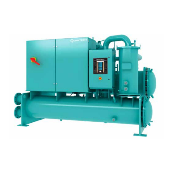
- Page 1 WATER-COOLED SCREW LIQUID CHILLERS INSTALLATION, OPERATION, MAINTENANCE New Release Form QWC4-NM1 (221) 035-28391-000 MODEL QWC4 SINGLE COMPRESSOR 60 HZ 120 TONS TO 200 TONS R-134a Issue Date: February 28, 2021...
- Page 2 All wiring must be in accordance with Quantech’ published specifications and must be performed only by a qualified electrician. Quantech will NOT be responsible for damage/problems resulting from improper con- nections to the controls or application of improper control signals.
- Page 3 Exchange website at https://docs.johnsoncontrols.com/ chillers/. ASSOCIATED LITERATURE MANUAL DESCRIPTION FORM NUMBER QWC4 Chiller Installation Checklist QWC4-CL1 QWC4 Chiller Start-up Checklist and Request for Authorized Start-up Technician QWC4-CL3 QWC4 Renewal Parts QWC4-RP1 Limited Warranty QTC-NM2 QUANTECH...
- Page 4 FORM QWC4-NM1 (221) ISSUE DATE: 02/28/2021 Nomenclature QWC4 0150 NOMINAL LEVEL PASS A=Evap: 1-pass; Cond: 1 pass APPLICATION B=Evap: 2-pass; Cond: 1 pass S=Std Water Chiller C=Evap: 3-pass; Cond: 1 pass COND D=Dry Tower/Radiator D=Evap: 1-pass; Cond: 2 pass TUBES* P=Process Brine E=Evap: 2-pass;...
-
Page 5: Table Of Contents
Fluorinated Greenhouse Gases ........................12 Responsibility for Safety ..........................12 Misuse of Equipment ............................12 SECTION 2 - PRODUCT DESCRIPTION ......................15 Components ..............................15 Semi-Hermetic Quantech Screw Compressors .....................19 Evaporator ..............................19 Condenser ..............................19 Refrigerant Circuit ............................19 Complete Factory Package ........................... 19 Electrical ................................ - Page 6 FORM QWC4-NM1 (221) ISSUE DATE: 02/28/2021 TABLE OF CONTENTS (CONT'D) Unit Piping ..............................57 Electrical Connection ............................57 Power Wiring ..............................57 Power Supply Wiring ............................57 115 VAC Control Supply Transformer ......................57 Control Wiring ..............................57 System Inputs ..............................58 Analog Inputs ..............................
- Page 7 FORM QWC4-NM1 (221) ISSUE DATE: 02/28/2021 TABLE OF CONTENTS (CONT'D) SECTION 8 - TROUBLESHOOTING .........................147 Abnormal Operation, Analysis and Correction ..................... 147 Troubleshooting the Compressor and Oil Separation System ..............147 SECTION 9 - DECOMMISSIONING, DISMANTLING, AND DISPOSAL ............153...
- Page 8 LIST OF FIGURES FIGURE 1 - Emergency Shutdown Handle ......................13 FIGURE 2 - QWC4 Chiller Major Components (Front View) ..................16 FIGURE 3 - QWC4 Chiller Major Components (Rear View) ...................17 FIGURE 4 - Basic System Control and VSD System Architecture .................18 FIGURE 5 - Control Center User Interface ......................20...
- Page 9 FIGURE 58 - Manual Override and Print Key .......................122 FIGURE 59 - Printer Cable Connection from QWC4 Chiller to a Computer ............122 FIGURE 60 - Printer Cable Connection from QWC4 Chiller to a Serial Printer ............ 123 FIGURE 61 - Sample Printout ..........................125 FIGURE 62 - System Switches and Service Keys ....................127...
- Page 10 TABLE 40 - Okidata OKIPOS 441 ........................123 TABLE 41 - Printout Types ...........................124 TABLE 42 - Real Time Number Errors .........................129 TABLE 43 - Operation/Inspection /Maintenance Requirements for QWC4 Chillers ..........131 TABLE 44 - Compressor Oil Limits ........................133 TABLE 45 - System Pressures ..........................140 TABLE 46 - Troubleshooting Guide ........................148...
-
Page 11: Section 1 - General Chiller Information And Safety
INTRODUCTION labor or extended warranty has been purchased as part Quantech QWC4 chillers are manufactured to the high- of the contract. est design and construction standards to ensure high performance, reliability, and adaptability to all types of The warranty is limited to parts only replacement and air conditioning installations. -
Page 12: Fluorinated Greenhouse Gases
FORM QWC4-NM1 (221) SECTION 1 - GENERAL CHILLER INFORMATION AND SAFETY ISSUE DATE: 02/28/2021 • GB/T 18430.1 - Water Chilling (Heat Pump) Pack- • Personal safety, the safety of other personnel, and ages Using The Vapor Compression Cycle - Part the equipment. -
Page 13: Figure 1 - Emergency Shutdown Handle
FORM QWC4-NM1 (221) SECTION 1 - GENERAL CHILLER INFORMATION AND SAFETY ISSUE DATE: 02/28/2021 Pressure Systems The unit contains refrigerant vapor and liquid under pres- sure, release of which can be a danger and cause injury. The user should make sure that care is taken during in- stallation, operation, and maintenance to avoid damage to the pressure system. - Page 14 FORM QWC4-NM1 (221) ISSUE DATE: 02/28/2021 THIS PAGE IS INTENTIONALLY LEFT BLANK. QUANTECH...
-
Page 15: Section 2 - Product Description
Quantech QWC4 chillers are designed for water or gly- COMPONENTS col cooling. All units are designed to be located in an The QWC4 chiller, as shown in Figure 2 on page 16 equipment room unless the unit was ordered specially and Figure 3 on page 17, consists of: for outside applications. -
Page 16: Figure 2 - Qwc4 Chiller Major Components (Front View)
ISSUE DATE: 02/28/2021 LD17364 1. Control Panel 5. Condenser 2. Variable Speed Drive (VSD) 6. Condenser Sight Glass 3. Oil Separator 7. Evaporator 4. Return Waterbox 8. Condenser Water Nozzle FIGURE 2 - QWC4 CHILLER MAJOR COMPONENTS (FRONT VIEW) QUANTECH... -
Page 17: Figure 3 - Qwc4 Chiller Major Components (Rear View)
SECTION 2 - PRODUCT DESCRIPTION ISSUE DATE: 02/28/2021 LD17365 1. VSD 5. Liquid Level Sensor 2. Compressor 6. Liquid Line 3. Evaporator Sight Glass 7. Condenser 4. Evaporator Water Nozzle 8. Evaporator FIGURE 3 - QWC4 CHILLER MAJOR COMPONENTS (REAR VIEW) QUANTECH... -
Page 18: Figure 4 - Basic System Control And Vsd System Architecture
FORM QWC4-NM1 (221) SECTION 2 - PRODUCT DESCRIPTION ISSUE DATE: 02/28/2021 INPUTS OUTPUTS Pressure Transducers (Relay Output Board) Temperature Sensors Switches Solenoids Liquid Flow Alarm CONTROL High Pressure Pump PANEL Start/Stop Compressor Heater (Chiller Control Level Run Status Board) Customer Supplied... -
Page 19: Semi-Hermetic Quantech Screw Compressors
The QWC4 compressor is one of evaporator and condenser to ensure each circuit func- the most efficient and reliable screw compressors in tions correctly. -
Page 20: Microcomputer Control Center
FORM QWC4-NM1 (221) SECTION 2 - PRODUCT DESCRIPTION ISSUE DATE: 02/28/2021 MICROCOMPUTER CONTROL CENTER The microcomputer control center, shown in Figure 5 on page 20, provides automatic control of chiller operation including compressor start/stop and load/un- load anti-recycle timers, condenser and chilled water (CHW) pumps, unit alarm contacts and run signal con- tacts. - Page 21 FORM QWC4-NM1 (221) SECTION 2 - PRODUCT DESCRIPTION ISSUE DATE: 02/28/2021 Double Thick Insulation 1 1/2 in. (38 mm) insulation servicing. Circuit breaker is sized to provide motor is available on the evaporator as a factory-installed op- branch, short circuit and ground fault protection for the tion.
-
Page 22: Figure 6 - Head Pressure Control System
The Head Pressure Control function provides an output QWC4 Chillers are capable of operation with- control signal that will respond to a programmed mini- in a wide range of condenser water tempera- mum chiller differential pressure. -
Page 23: Section 3 - Handling, Storage, Installation, And Reassembly
Observe the following precautions: all units are tested and inspected before leaving the fac- • Notify the nearest Quantech office in ample time tory. The chiller may be ordered and shipped in any of for a Quantech representative to observe rigging... - Page 24 • All openings on the shells are closed and charged removed from the shells and skidded separately. with a 2 psig to 3 psig (115 kPa to 122 kPa) hold- Form 7 QWC4 chillers are shipped in the following as- ing charge of dry nitrogen. semblies: •...
-
Page 25: Inspection, Damage, And Shortage
• If the unit is stored longer than six months, follow ny's inspection. the requirements from Long-Term Storage Peri- odic Checklist and Logs for QWC4 Screw Chillers Quantech will not be responsible for any (Form 50.20-NM9). damage or loss of parts in shipment or at job site. -
Page 26: Lifting Weights
1129– 408–430 185–195 9515 4316 10421 4727 2606 1182 NOTE: Weights shown for base unit; selected options and tube count variations may add weights and/or refrigerant charge quantity to unit. Contact your nearest Quantech Sales Office for weight data. QUANTECH... -
Page 27: Moving The Chiller For Forms 1 And 2
FORM QWC4-NM1 (221) SECTION 3 - HANDLING, STORAGE, INSTALLATION, AND REASSEMBLY ISSUE DATE: 02/28/2021 MOVING THE CHILLER FOR FORMS 1 AND 2 RIGGING Before moving the unit, make sure that the installation The complete standard unit (Forms 1 and 2) is shipped site is suitable for installing the unit and is easily ca- without skids. -
Page 28: Foundation
FORM QWC4-NM1 (221) SECTION 3 - HANDLING, STORAGE, INSTALLATION, AND REASSEMBLY ISSUE DATE: 02/28/2021 LOCATION TABLE 2 - SERVICE CLEARANCE REQUIRE- MENTS Locate the chiller in an indoor location with tempera- TUBE REMOVAL ADD MARINE ture ranges from 40°F to 110°F (4°C to 43°C) and ad-... -
Page 29: Installing Elastomeric Vibration Isolator Pads
FORM QWC4-NM1 (221) SECTION 3 - HANDLING, STORAGE, INSTALLATION, AND REASSEMBLY ISSUE DATE: 02/28/2021 INSTALLING ELASTOMERIC VIBRATION ISOLATOR PADS Locate the elastomeric vibration isolator pads as shown The unit should be level within 0.25 in. (6 mm) from in Figure 9 on page 29 After placing the isolator one end to the other end, and from front to the rear. -
Page 30: Installing Optional Spring Isolators
FORM QWC4-NM1 (221) SECTION 3 - HANDLING, STORAGE, INSTALLATION, AND REASSEMBLY ISSUE DATE: 02/28/2021 INSTALLING OPTIONAL SPRING ISOLATORS enough to level unit due to an uneven or sloping If ordered, four identical spring type isolator assemblies floor or foundation, add as many shims as neces- are furnished with the unit as shown in Figure 10 on sary (grouted, if necessary) under the isolator. -
Page 31: Form 7 Reassembly
2. For wiring connections, refer to Field Connec- ances. See Figure 8 on page 28. tions and Control Wiring for QWC4 Chiller 2. Rig the evaporator and place in the final location (QWC4-PW2). -
Page 32: Table 4 - Torque Specification
FORM QWC4-NM1 (221) SECTION 3 - HANDLING, STORAGE, INSTALLATION, AND REASSEMBLY ISSUE DATE: 02/28/2021 TABLE 4 - TORQUE SPECIFICATION UNIT QUANTECH TORQUE VALUE ITEM DESCRIPTION PART QUANTITY NUMBER FT-LBS. NUMBER END SHEETS (CON-EVAP ASSY) HCS5 0.625-11 X 2.500 GR 5 ZN... -
Page 33: Figure 11 - Rigging The Evaporator
FORM QWC4-NM1 (221) SECTION 3 - HANDLING, STORAGE, INSTALLATION, AND REASSEMBLY ISSUE DATE: 02/28/2021 Installing the Evaporator Use the following instructions to install the evaporator 1. Attach the rigging chains from the overhead lift to as shown in Figure 11 on page 33. -
Page 34: Figure 12 - Condenser Rigging
FORM QWC4-NM1 (221) SECTION 3 - HANDLING, STORAGE, INSTALLATION, AND REASSEMBLY ISSUE DATE: 02/28/2021 Rigging and Installing the Condenser 1. Attach the rigging chains from the overhead lift to Use the following instructions to install the condenser the four lifting holes of the condenser (two at the as shown in Figure 12 on page 34. -
Page 35: Figure 13 - Isolator Installation
FORM QWC4-NM1 (221) SECTION 3 - HANDLING, STORAGE, INSTALLATION, AND REASSEMBLY ISSUE DATE: 02/28/2021 Installing the Pads or Spring Isolators Use the following instructions to install the elastomeric 2. With an adequate lifting device lift the unit slight- pads or optional spring isolators as shown on page 36. - Page 36 FORM QWC4-NM1 (221) SECTION 3 - HANDLING, STORAGE, INSTALLATION, AND REASSEMBLY ISSUE DATE: 02/28/2021 LD16471 FIGURE 12 - ISOLATOR INSTALLATION (CONT'D) QUANTECH...
-
Page 37: Figure 14 - Heat Exchanger Shipping Brackets
FORM QWC4-NM1 (221) SECTION 3 - HANDLING, STORAGE, INSTALLATION, AND REASSEMBLY ISSUE DATE: 02/28/2021 Installing the Heat Exchanger Piping Use the following instructions after the temporary ship- Connect the economizer heat exchanger liquid outlet pipes to the economizer on the evaporator, using the ping brackets supporting the heat exchanger piping has been removed as shown in Figure 14 on page 37. -
Page 38: Figure 16 - Liquid Injection Piping
FORM QWC4-NM1 (221) SECTION 3 - HANDLING, STORAGE, INSTALLATION, AND REASSEMBLY ISSUE DATE: 02/28/2021 Installing the Liquid Injection Piping Installing Oil Return Piping If equipped, install the optional liquid injection piping Install the oil return and piping between the filter drier... -
Page 39: Figure 18 - Driveline (Compressor/Motor) Assembly
FORM QWC4-NM1 (221) SECTION 3 - HANDLING, STORAGE, INSTALLATION, AND REASSEMBLY ISSUE DATE: 02/28/2021 Installing Driveline Assembly Specific shim pads will be bolted to the Use the following instructions to install the driveline compressor supports to satisfy the align- (compressor/motor) assembly as shown in Figure 18 ment between the compressor and system on page 39. -
Page 40: Table 8 - Oil Separator Weight And Dimensions On Single Compressor Units
FORM QWC4-NM1 (221) SECTION 3 - HANDLING, STORAGE, INSTALLATION, AND REASSEMBLY ISSUE DATE: 02/28/2021 Installing Oil Separator 2. Bolt the line to the flange on the oil separator and Use the following instructions to install the oil separator, to compressor discharge using the proper gaskets as shown in Figure 19 on page 41. -
Page 41: Figure 19 - Oil Separator Discharge Piping On Single Compressor Units
FORM QWC4-NM1 (221) SECTION 3 - HANDLING, STORAGE, INSTALLATION, AND REASSEMBLY ISSUE DATE: 02/28/2021 With Isolation Ball Valve LD17759 See Table 4 on page 32 for Torque Specifications. FIGURE 19 - OIL SEPARATOR DISCHARGE PIPING ON SINGLE COMPRESSOR UNITS QUANTECH... -
Page 42: Figure 20 - Transducer, Eductor And Oil Return Piping
FORM QWC4-NM1 (221) SECTION 3 - HANDLING, STORAGE, INSTALLATION, AND REASSEMBLY ISSUE DATE: 02/28/2021 Oil Return Oil Return Pressure Pressure from Eductor from Eductor Transducer Transducer Oil Return Oil Return from Oil Separator from Oil Separator 136/145 Compressor Ports 151 Compressor Ports LD17760 See Table 4 on page 32 for Torque Specifications. -
Page 43: Table 9 - Vsd Weight And Dimensions
FORM QWC4-NM1 (221) SECTION 3 - HANDLING, STORAGE, INSTALLATION, AND REASSEMBLY ISSUE DATE: 02/28/2021 Installing Variable Speed Drive (VSD) Use a spreader bar to ensure that the lift- Use the following instructions to install the VSD as ing chains do not bend the lifting tongs shown in Figure 22 on page 44. -
Page 44: Figure 22 - Variable Speed Drive (Vsd)
FORM QWC4-NM1 (221) SECTION 3 - HANDLING, STORAGE, INSTALLATION, AND REASSEMBLY ISSUE DATE: 02/28/2021 65° Min. Lifting Holes LD17762 See Table 4 on page 32 for Torque Specifications. FIGURE 22 - VARIABLE SPEED DRIVE (VSD) Installing Control Panel Connecting VSD Cooling Hoses... -
Page 45: Figure 23 - Control Panel
FORM QWC4-NM1 (221) SECTION 3 - HANDLING, STORAGE, INSTALLATION, AND REASSEMBLY ISSUE DATE: 02/28/2021 See Table 4 on page 32 for Torque Specifications. FIGURE 23 - CONTROL PANEL Detail A LD17764 CONDENSER LD17763 FIGURE 24 - VSD COOLING HOSES QUANTECH... -
Page 46: Piping Joint Assembly
FORM QWC4-NM1 (221) SECTION 3 - HANDLING, STORAGE, INSTALLATION, AND REASSEMBLY ISSUE DATE: 02/28/2021 Evaporator Condenser Evaporator Condenser Only be used for heat pump unit Only be used for standard air-conditioning ice storage unit and brine unit LD18956 FIGURE 25 - ALTERNATE PIPING FOR VSD... -
Page 47: Gasket Joints
FORM QWC4-NM1 (221) SECTION 3 - HANDLING, STORAGE, INSTALLATION, AND REASSEMBLY ISSUE DATE: 02/28/2021 PROCEDURES GASKET JOINTS Cleaning Assembling Gasket Joints Clean the parts visually contaminated with oil, grease, Use the following instructions to assemble the gasket or dirt with a generous spray of cleaner 7070. Wipe joints. -
Page 48: Torque Values
FORM QWC4-NM1 (221) SECTION 3 - HANDLING, STORAGE, INSTALLATION, AND REASSEMBLY ISSUE DATE: 02/28/2021 Torque Values Sealing is thus affected and maintained by the O-ring All threaded fasteners shall be torqued to the values compression which results from the clamping force shown in Table 13 on page 48 for the appropriate generated by tightening. -
Page 49: Figure 28 - Back Off Locknut
FORM QWC4-NM1 (221) SECTION 3 - HANDLING, STORAGE, INSTALLATION, AND REASSEMBLY ISSUE DATE: 02/28/2021 Back off locknut as far as possible. Make sure back-up 7. Inspect to ensure that O-ring is NOT pinched and washer is NOT loose and is pushed up as far as pos- the back-up washer seats flat on face of port. -
Page 50: Brazed Joints
FORM QWC4-NM1 (221) SECTION 3 - HANDLING, STORAGE, INSTALLATION, AND REASSEMBLY ISSUE DATE: 02/28/2021 Assembly of O-ring Face Seal Fittings BRAZED JOINTS For personnel safety: Do not perform any The male end and female nut of face seal fittings have brazing or heat working unless the refrig- UN/UNF straight threads. -
Page 51: Figure 32 - Brazed Joints
FORM QWC4-NM1 (221) SECTION 3 - HANDLING, STORAGE, INSTALLATION, AND REASSEMBLY ISSUE DATE: 02/28/2021 TABLE 15 - O-RING ASSEMBLY TORQUE SPECIFICATIONS TUBE SAE STRAIGHT SAE STRAIGHT THREAD FACE SEAL TUBE-SIDE FACE SEAL TUBE- SIZE THREAD TORQUE SIZE (O-RING P/N) THREAD SIZE (O-RING P/N) SIDE TORQUE (FT-LB) (IN.) -
Page 52: Piping Connections
NPT connection can be ob- will likely show up as error in the sensor. tained from Quantech as an accessory for the unit. Al- As a precautionary measure, remove the ternatively, a differential pressure switch fitted across... -
Page 53: Water Treatment
Consult a water treatment specialist to deter- loads, and at off-peak seasons of the year. QWC4 chill- mine if the proposed water composition will adversely ers can be operated with entering condensing water affect the evaporator materials of carbon steel and cop- temperature that is less than design conditions. -
Page 54: Pipework Arrangement
RATIO RANGE Air Conditioning 5–8 (min of 5) 5.5–8.8 (min of 3.3) The QWC4 chiller line has a maximum leaving Process 7–11 (min of 7) 7.7–12.3 (min of 4.4) water temperature of 60°F (15.6°C). Where process Install a tank or increase pipe sizes to provide suffi- applications require a chilled water temperature higher cient water volume. -
Page 55: Nozzle Connections
American other design issues to evaluate with variable primary Society of Heating, Refrigeration and Air Conditioning flow systems. Consult the Quantech Sales Office for Engineers Standard 15 (ASHRAE 15) in North Amer- more information about successfully applying QWC4 ica, or PED code in Europe. -
Page 56: Figure 37 - Typical Components Of Relief Piping
FORM QWC4-NM1 (221) SECTION 3 - HANDLING, STORAGE, INSTALLATION, AND REASSEMBLY ISSUE DATE: 02/28/2021 When installing relief piping an ANSI flange or a piping union must be used to make a servicable piping connection. Horizontal Vertical Compressed Mis-aligned Offset When installing relief piping there must NOT be any piping strain. -
Page 57: Unit Piping
Alumi- supervision of a Quantech representative, using fur- num oxide may also build up at the termination, which nished material. -
Page 58: System Inputs
FORM QWC4-NM1 (221) SECTION 3 - HANDLING, STORAGE, INSTALLATION, AND REASSEMBLY ISSUE DATE: 02/28/2021 the panel end only, and run in water tight conduit. Run Remote Run Permissive shielded cable separately from mains cable to avoid A remote run permissive input is available and requires electrical noise pick-up. - Page 59 The function of the input is controlled by se- the unit, contact the Quantech Field Service Office to lecting the operating mode described in SECTION 6 schedule the start-up service.
- Page 60 2. Unit assembled (if shipped dismantled) and re- NOTE: DO NOT cut to length or connect to frigerant piping installed ........drive without Quantech supervision ....3. Vibration isolator mounted so that the unit is 2. External control wiring completed according to level and isolators are equally deflected .....
- Page 61 Year We understand that the services of the Quantech Authorized Representative will be furnished in accordance with the contract for a period of time of not more than _______ consecutive normal working hours, and we agree that a charge of _________ per diem plus travel expenses will be made to Quantech if services are required for longer than ________ consecutive normal hours or if repeated calls are required, through no fault of Quantech.
-
Page 62: Figure 38 - Power Connections
FORM QWC4-NM1 (221) SECTION 3 - HANDLING, STORAGE, INSTALLATION, AND REASSEMBLY ISSUE DATE: 02/28/2021 FIELD PROVIDED UNIT POWER SUPPLY SEE NOTE 1 VSD CONTROL PANEL STANDARD UNIT CONTROLS CONTROL TRANSFORMER NON-FUSED DISCONNECT SWITCH LINE REACTOR CIRCUIT BREAKER OPTION AVAILABLE INVERTER... -
Page 63: Table 21 - Lug Data (Ul/Asme/Ce) - Pin 22/Power Field
FORM QWC4-NM1 (221) SECTION 3 - HANDLING, STORAGE, INSTALLATION, AND REASSEMBLY ISSUE DATE: 02/28/2021 TABLE 21 - LUG DATA (UL/ASME) - PIN 22/POWER FIELD NON-FUSED VSD DETAILS TERMINAL BLOCK CIRCUIT BREAKER DISCONNECT SWITCH WIRES WIRES WIRES INPUT INPUT LUG/ LUG/... - Page 64 FORM QWC4-NM1 (221) ISSUE DATE: 02/28/2021 THIS PAGE IS INTENTIONALLY LEFT BLANK. QUANTECH...
-
Page 65: Section 4 - Technical Data
FORM QWC4-NM1 (221) ISSUE DATE: 02/28/2021 SECTION 4 - TECHNICAL DATA TABLE 23 - COMPLETE PIN NUMBER DESCRIPTION DESCRIPTION OPTIONS OPTIONS DESCRIPTION MODEL QWC4 Quantech Evaporator Sizes EVAPORATOR MODEL Condenser Sizes CONDENSER MODEL WTS45/CTS45 9-10 COMPRESSOR DRIVELINE WTS51/CTS51 Starter Size STARTER Evap: 1pass;... - Page 66 FORM QWC4-NM1 (221) SECTION 4 - TECHNICAL DATA ISSUE DATE: 02/28/2021 TABLE 24 - COMPLETE PIN NUMBER DESCRIPTION (CONT'D) DESCRIPTION OPTIONS OPTIONS DESCRIPTION 380/3/60 460/3/60 20-21 VOLTAGE 380/3/50 400/3/50 415/3/50 Lockable NF Disconnect Switch Lockable Circuit Breaker POWER FIELD Supply Terminal Block...
- Page 67 FORM QWC4-NM1 (221) SECTION 4 - TECHNICAL DATA ISSUE DATE: 02/28/2021 TABLE 24 - COMPLETE PIN NUMBER DESCRIPTION (CONT'D) DESCRIPTION OPTIONS OPTIONS DESCRIPTION Chinese Safety Code (GB) European Safety Code (CE) SAFETY CODE NA Safety Code (cUL/cETL) Special Quote No Selection...
- Page 68 FORM QWC4-NM1 (221) SECTION 4 - TECHNICAL DATA ISSUE DATE: 02/28/2021 TABLE 24 - COMPLETE PIN NUMBER DESCRIPTION (CONT'D) DESCRIPTION OPTIONS OPTIONS DESCRIPTION None 3/4 in. insulation evaporator 1 1/2 in. insulation evaporator THERMAL INSULATION 3/4 in. insulation evap and cond 1 1/2 in.
- Page 69 FORM QWC4-NM1 (221) SECTION 4 - TECHNICAL DATA ISSUE DATE: 02/28/2021 TABLE 24 - COMPLETE PIN NUMBER DESCRIPTION (CONT'D) DESCRIPTION OPTIONS OPTIONS DESCRIPTION Water Calcium Chloride Sodium Chloride EVAPORATOR FLUID Ethylene Glycol Propylene Glycol Special Quote No Selection FUTURE OPTIONS...
-
Page 70: Table 24 - Complete Pin Number Description
FORM QWC4-NM1 (221) SECTION 4 - TECHNICAL DATA ISSUE DATE: 02/28/2021 TABLE 24 - COMPLETE PIN NUMBER DESCRIPTION (CONT'D) DESCRIPTION OPTIONS OPTIONS DESCRIPTION Water Calcium Chloride Sodium Chloride CONDENSER FLUID Ethylene Glycol Propylene Glycol Special Quote 235 psig (1.62 MPa) - Page 71 FORM QWC4-NM1 (221) SECTION 4 - TECHNICAL DATA ISSUE DATE: 02/28/2021 TABLE 24 - COMPLETE PIN NUMBER DESCRIPTION (CONT'D) DESCRIPTION OPTIONS OPTIONS DESCRIPTION No SR Documents Monterrey base document Monterrey base & materials doc Sabadell base document Sabadell base & optional doc...
-
Page 72: Single Compressor Unit Dimensions
FORM QWC4-NM1 (221) SECTION 4 - TECHNICAL DATA ISSUE DATE: 02/28/2021 SINGLE COMPRESSOR UNIT DIMENSIONS TOP VIEW LD16476a SIDE VIEW FRONT VIEW LD16476b LD16476d FIGURE 39 - SINGLE COMPRESSOR UNIT DIMENSIONS QUANTECH... - Page 73 FORM QWC4-NM1 (221) SECTION 4 - TECHNICAL DATA ISSUE DATE: 02/28/2021 EVAPORATOR AND CONDENSER SHELL CODES IN (MM) DIMENSIONS SINGLE 145/151 DUAL 136/145 8ˊ (2438) 10ˊ (3048) 12ˊ (3658) 12' (3658) 14' (4268) 6ˊ-11/16" (1846) 6ˊ-11/16" (1846) 6ˊ-11/16" (1846) 6'-3/4" (1844) 6'-3/4"...
-
Page 74: Dimensions Of Evaporator Nozzle Arrangements
FORM QWC4-NM1 (221) SECTION 4 - TECHNICAL DATA ISSUE DATE: 02/28/2021 DIMENSIONS OF EVAPORATOR NOZZLE ARRANGEMENTS NOZZLE ARRANGEMENTS EVAPORATOR (PIN 5,6) NUMBER OF PASSES LD16477a FIGURE 40 - EVAPORATORS - COMPACT WATERBOXES (2-PASS) NOZZLE ARRANGEMENTS EVAPORATOR (PIN 5,6) NUMBER OF PASSES... -
Page 75: Dimensions Of Condenser Nozzle Arrangements
FORM QWC4-NM1 (221) SECTION 4 - TECHNICAL DATA ISSUE DATE: 02/28/2021 DIMENSIONS OF CONDENSER NOZZLE ARRANGEMENTS NOZZLE ARRANGEMENTS CONDENSER (PIN 7,8) NUMBER OF PASSES LD16478a FIGURE 42 - CONDENSERS - COMPACT WATERBOXES (1-PASS) NOZZLE ARRANGEMENTS CONDENSER (PIN 7,8) NUMBER OF PASSES... -
Page 76: Table 27 - Water Flow Rate Limits Gpm (L/S) (Based Upon Standard Tubes At Design Full Load Conditions)
FORM QWC4-NM1 (221) SECTION 4 - TECHNICAL DATA ISSUE DATE: 02/28/2021 TABLE 26 - WATER FLOW RATE LIMITS GPM (L/S) (BASED UPON STANDARD TUBES AT DESIGN FULL LOAD CONDITIONS) EVAPORATOR CONDENSER PIN 5, 6 2 PASS 3 PASS PIN 7, 8... -
Page 77: Section 5 - Commissioning
Make sure all checks are completed in the Start-up lower and middle of the upper sight glass of the oil Checklist (Form QWC4-CL3) on the next page. The separator. chiller is then ready to be placed into operation. - Page 78 ........... shipped loose with the chiller. Refer to SEC- 4. Wiring is complete (power feed terminations in TION 7 - MAINTENANCE in the QWC4-NM1 for the VSD), and all sources of electrical supply to filling process............. the unit are taken from a single point of isolation 10.
- Page 79 WARNING message appears, immediately con- This sensor must always be fully inserted in the tact QuanTech Product Technical Support to water outlet sensor well........request the password to reprogram the serial number, and any other important factory pro- 17.
- Page 80 Refer to the PROGRAM 4. If the chilled and condenser liquid pumps are key in SECTION 6 - OPERATION in QWC4-NM1 for low and high limits, and default values. manually operated, start the pumps. The con- trol center will not allow the chiller to start un- 1.
- Page 81 FORM QWC4-NM1 (221) SECTION 5 - COMMISSIONING ISSUE DATE: 02/28/2021 FORM QWC4-CL3 ISSUE DATE: 02/28/2021 9. When the compressor starts, press the relevant System Pressures key to verify that oil differen- tial pressure develops immediately. If oil pres- sure does not develop, the automatic controls will shut down the compressor.
- Page 82 FORM QWC4-NM1 (221) ISSUE DATE: 02/28/2021 THIS PAGE IS INTENTIONALLY LEFT BLANK. QUANTECH...
-
Page 83: Section 6 - Operation
FORM QWC4-NM1 (221) ISSUE DATE: 02/28/2021 SECTION 6 - OPERATION Keypad OPERATING CONTROLS DISPLAY An operator keypad allows complete control of the sys- tem from a central location. Access the following command keys on the left and right side of the keypad: •... -
Page 84: Basic Operating Sequence
FORM QWC4-NM1 (221) SECTION 6 - OPERATION ISSUE DATE: 02/28/2021 Use the ▲,▼,◄, and ► keys to see the multiple dis- BASIC OPERATING SEQUENCE plays under a key. Once the ▲ ▼ keys are pressed and Start Sequence and Loading... -
Page 85: Figure 46 - Control Operation
FORM QWC4-NM1 (221) SECTION 6 - OPERATION ISSUE DATE: 02/28/2021 • A low leaving chilled liquid temperature fault Remote Run Permissive Input occurs. The run permissive switches must have electrical con- • The VSD is requested to precharge for a run. -
Page 86: Table 28 - Load Limiting Values
If there are questions about the following reset con- RESET analog input. A zero signal input (0%) trols, contact a Quantech BAS representative for de- equates to a 0°F (0°C) offset to the local setpoint. tails on BAS controls and capabilities. - Page 87 0°F (0°C) offset to the local setpoint. A full scale problems with chilled liquid temperature control. signal input (100%) equates to a negative offset A Quantech Factory Service Center should be to the local setpoint equal to the programmable contacted if a timer change is required.
-
Page 88: User Interface
15 minutes will create problems with chilled liquid tempera- • Remote Current Limit Analog Reset: Set the ture control. Contact a Quantech Factory Service CURRENT LIMIT setpoint via the REMOTE Center if a timer change is required. -
Page 89: Figure 47 - Status Key
STATUS message. When in this mode, no other STATUS messages can be seen. When power is first applied to the control panel, the following message displaying Quantech, EPROM ver- UNIT STATUS sion, date, and time will be displayed for two seconds,... - Page 90 FORM QWC4-NM1 (221) SECTION 6 - OPERATION ISSUE DATE: 02/28/2021 rator pressure and overcome low differential pressure UNIT STATUS to maintain oil flow. CONDENSER LIQUID FLOW SWITCH SHUTDOWN The flow switch is open, which is preventing the unit Load or Unloading Limit Messages from running.
-
Page 91: Fault Messages
FORM QWC4-NM1 (221) SECTION 6 - OPERATION ISSUE DATE: 02/28/2021 FAULT MESSAGES problems since it allows the service technician to view A number of possible fault messages may appear when operating parameters before a unit fault. Details on the the STATUS key is pressed. Whenever a fault message... -
Page 92: Figure 48 - New 331-03478-Xxx Microboard
FORM QWC4-NM1 (221) SECTION 6 - OPERATION ISSUE DATE: 02/28/2021 TP4 +12 V TP10 +24 V TP5 +15 V TP1 GND Port 1 Future Native U26 Port 1 RS-485 Driver +3.3V U18 VSD RS-485 Driver Card VSD RX VSD TX... -
Page 93: Program Update
FORM QWC4-NM1 (221) SECTION 6 - OPERATION ISSUE DATE: 02/28/2021 JP6 Remote Sound Limit jumper position (Pins 1 to 2 3. Turn the Unit Switch OFF. (left) = 4 mA to 20 mA, Pins 2 to 3 (right) = 0 VDC to 4. -
Page 94: Data Logging
ENTER key. curred on March 3rd at 2:05pm, the user can import the Again, follow the Quantech Safety Directives to stop 20150303.csv file into Excel and look at the system the chiller, power off the unit and open the control cab- parameter details leading up to the 2:05pm event. -
Page 95: Table 31 - Unit Warnings
Contact INVALID SERIAL Quantech Product Technical Support immediately to get the password to enter the serial number NUMBER using the SERVICE key. Bypass this status message to view additional messages by pressing the STATUS key repeatedly. - Page 96 FORM QWC4-NM1 (221) SECTION 6 - OPERATION ISSUE DATE: 02/28/2021 Unit safeties (faults), as shown in Table 32 on page First Fault Code 97, are: The first fault code will be set for the fault that initiated the system shutdown.
-
Page 97: Table 32 - Unit Safeties (Faults)
FORM QWC4-NM1 (221) SECTION 6 - OPERATION ISSUE DATE: 02/28/2021 TABLE 31 - UNIT SAFETIES (FAULTS) MESSAGE DESCRIPTION Software-Initiated Fault - The voltage magnitude of each half of the DC bus shall remain within UNIT YYYYYYY +/- 100 VDC of the total DC bus voltage divided by two. If the magnitude exceeds the +/- 100 volt window the unit shall initiate a shutdown. - Page 98 FORM QWC4-NM1 (221) SECTION 6 - OPERATION ISSUE DATE: 02/28/2021 TABLE 32 - UNIT SAFETIES FAULTS (CONT'D) MESSAGE DESCRIPTION The voltage magnitude of each half of the DC bus shall remain within +/- 100 VDC of the total UNIT YYYYYYY DC bus voltage divided by two.
-
Page 99: Table 33 - System Safeties (Faults)
FORM QWC4-NM1 (221) SECTION 6 - OPERATION ISSUE DATE: 02/28/2021 TABLE 32 - UNIT SAFETIES FAULTS (CONT'D) MESSAGE DESCRIPTION Hardware-Initiated Fault - The various DC power supplies which power the logic board are monitored via hardware located on the logic board. If any power supply falls outside its allowable limits, the unit initiates a shutdown. - Page 100 FORM QWC4-NM1 (221) SECTION 6 - OPERATION ISSUE DATE: 02/28/2021 TABLE 33 - SYSTEM SAFETIES FAULTS (CONT'D) MESSAGE DESCRIPTION Software-Initiated Fault - A system will fault and shut down with a ramped shutdown when the high discharge pressure rises above 333 psig (2300 kPa) for 0.5 seconds. The system will be allowed to restart when the discharge pressure falls to 293 psig (20.2 kPa).
-
Page 101: Table 34 - Hpco Mechanical Cutouts
FORM QWC4-NM1 (221) SECTION 6 - OPERATION ISSUE DATE: 02/28/2021 TABLE 33 - SYSTEM SAFETIES FAULTS (CONT'D) MESSAGE DESCRIPTION Hardware-Initiated Fault - The mechanical High Pressure Cutout (HPCO) protects the system from experiencing dangerously high discharge pressure. A system will fault and shut down immediately when the mechanical high pressure cutout contacts open. - Page 102 FORM QWC4-NM1 (221) SECTION 6 - OPERATION ISSUE DATE: 02/28/2021 TABLE 33 - SYSTEM SAFETIES FAULTS (CONT'D) MESSAGE DESCRIPTION This fault protects against excessive liquid refrigerant carryover from the economizer, in cases which may be a result of EEV, sensor or other problems. It also protects the system compressor from liquid refrigerant flooding back from the economizer feed line, in cases where the economizer valve fails to close.
- Page 103 FORM QWC4-NM1 (221) SECTION 6 - OPERATION ISSUE DATE: 02/28/2021 TABLE 33 - SYSTEM SAFETIES FAULTS (CONT'D) MESSAGE DESCRIPTION This fault is considered active when SMART FREEZE is turned on via the enable/disable setting, and the active LCHLT control setpoint is less than or equal to 38.0°F (3.3°C). SMART FREEZE can only be enabled or disabled while the chiller is stopped, and is only available in water applications.
-
Page 104: Figure 49 - Unit Data Key
FORM QWC4-NM1 (221) SECTION 6 - OPERATION ISSUE DATE: 02/28/2021 UNIT DATA KEY UNIT DATA KEY FIGURE 49 - UNIT DATA KEY LD19539 The UNIT DATA key displays unit temperatures, and UNIT EVAP/COND PUMP RUN = ON OR OFF related data. Select the displays, which are listed se-... -
Page 105: Figure 50 - System Data Key
FORM QWC4-NM1 (221) SECTION 6 - OPERATION ISSUE DATE: 02/28/2021 SYSTEM DATA KEY SYSTEM DATA KEY FIGURE 50 - SYSTEM DATA KEY LD19539 System Data Key Operation The SYSTEM DATA key gives access to SYSTEM operating parameters. The following list shows the data in the order in which they appear. -
Page 106: Table 36 - Sensor Minimum/Maximum Outputs
FORM QWC4-NM1 (221) SECTION 6 - OPERATION ISSUE DATE: 02/28/2021 Display, if control is enabled. Sensor Displays Table 36 on page 106 lists all the sensors attached VI STEP SOLENOID 1 = ON OR OFF to the control board associated with SYSTEM DATA VI STEP SOLENOID 2 = ON OR OFF keys. -
Page 107: Figure 51 - Vsd Data And Operating Hours/Start Counter Keys
FORM QWC4-NM1 (221) SECTION 6 - OPERATION ISSUE DATE: 02/28/2021 VSD DATA AND OPERATING HOURS/START COUNTER KEYS VSD DATA OPERATING HOURS/START COUNTER KEY LD19539 FIGURE 51 - VSD DATA AND OPERATING HOURS/START COUNTER KEYS The VSD DATA key provides multiple displays of VSD IGBT BASEPLATE TEMPS T1 = ### °F... -
Page 108: Figure 52 - History Key
FORM QWC4-NM1 (221) SECTION 6 - OPERATION ISSUE DATE: 02/28/2021 HISTORY KEY HISTORY LD19539 FIGURE 52 - HISTORY KEY For all faults generated by the control To access the HISTORY FAULT or NORMAL SHUT- DOWN information, use the following steps:... - Page 109 FORM QWC4-NM1 (221) SECTION 6 - OPERATION ISSUE DATE: 02/28/2021 If there are no ALL FAULTS for the current history, • OPTIONS on page 118 the following message will be displayed for the ALL • Display Language FAULTS screen. • Liquid Type, etc.
-
Page 110: Figure 53 - Setpoints Key
FORM QWC4-NM1 (221) SECTION 6 - OPERATION ISSUE DATE: 02/28/2021 SETPOINTS KEY SETPOINTS KEY LD19539 FIGURE 53 - SETPOINTS KEY Press the SETPOINTS key to program: This message (above) will display the remote setpoint and control, which automatically updates. If there is •... -
Page 111: Figure 54 - Setpoint High And Low Limits Defined By Control Range (Cr)
FORM QWC4-NM1 (221) SECTION 6 - OPERATION ISSUE DATE: 02/28/2021 TABLE 36 - SETPOINT VALUES PROGRAM VALUE MODE LOW LIMIT HIGH LIMIT DEFAULT 38.0°F 60.0°F 44.0°F Water Cooling 3.3°C 15.6°C 6.7°C Leaving Chilled Liquid Temp Setpoint 14.0°F 70.0°F 44.0°F Glycol Cooling -10.0°C... -
Page 112: Figure 55 - Program Key
FORM QWC4-NM1 (221) SECTION 6 - OPERATION ISSUE DATE: 02/28/2021 PROGRAM KEY PROGRAM KEY LD19539 FIGURE 55 - PROGRAM KEY Press the PROGRAM key to modify the following nu- PROGRAM ◄DEF 103 LO 30 HI 103 meric operating parameters, which are displayed when... -
Page 113: Table 38 - Program Limits
FORM QWC4-NM1 (221) SECTION 6 - OPERATION ISSUE DATE: 02/28/2021 PROGRAM HPC DIRECTION PROGRAM ◄DEF 0.0% LO 0.0% HI 100.0% ◄► XXXXXXXXXXXXXXXXXXXXXXXXXXXX HPC SHUTDOWN POSITION = XX.X PROGRAM ◄DEF 0.0% LO 0.0% HI 100.0% HPC MINIMUM POSITION = XX.X TABLE 37 - PROGRAM LIMITS... - Page 114 FORM QWC4-NM1 (221) SECTION 6 - OPERATION ISSUE DATE: 02/28/2021 Table 39 on page 116 - Setup Mode Programmable SETUP MODE ◄DEF 50.0 LO 50.0 HI 95.0 Values lists the values that can be programmed in this MIN START FREQ SETP = ##.# HZ...
- Page 115 FORM QWC4-NM1 (221) SECTION 6 - OPERATION ISSUE DATE: 02/28/2021 SETUP MODE ◄DEF 2.0 LO 0.1 HI 10.0 SETUP MODE VI STEP VALVE LVL CTRL INCREMENT 1 SETP = ##.# % ◄► ENABLED SETUP MODE ◄DEF 0.5 LO 0.1 HI 10.0 SETUP MODE ◄DEF 195.0...
-
Page 116: Table 39 - Setup Mode Programmable
FORM QWC4-NM1 (221) SECTION 6 - OPERATION ISSUE DATE: 02/28/2021 TABLE 38 - SETUP MODE PROGRAMMABLE SETUP MODE VALUE LOW LIMIT HIGH LIMIT DEFAULT Compressor 1 Operating Hours 99999 Compressor 1 Starts 99999 Total Kilowatt Hours 99999 Clear History Buffers —... - Page 117 FORM QWC4-NM1 (221) SECTION 6 - OPERATION ISSUE DATE: 02/28/2021 TABLE 39 - SETUP MODE PROGRAMMABLE (CONT'D) SETUP MODE VALUE LOW LIMIT HIGH LIMIT DEFAULT Oil Differential Condenser Level Control Setpoint 20.0 psid 30.0 psid 24 psid Level Control Decrement 1 0.10%...
-
Page 118: Figure 56 - Options Key
FORM QWC4-NM1 (221) SECTION 6 - OPERATION ISSUE DATE: 02/28/2021 OPTIONS KEY OPTIONS KEY LD19539 FIGURE 56 - OPTIONS KEY The OPTIONS key displays unit configuration and the Remote Temperature Reset Input capability to modify it. To view the current settings, The display will only appear if the TEMP RESET op- press this key. - Page 119 FORM QWC4-NM1 (221) SECTION 6 - OPERATION ISSUE DATE: 02/28/2021 Remote Current Limit Input Choose one LIMIT INPUT below, default is DIS- ABLED: OPTIONS REMOTE CURRENT LIMIT INPUT ◄ ► DISABLED OPTIONS REMOTE CURRENT LIMIT INPUT ◄ ► 0.0 TO 10.0 VOLTS DC...
-
Page 120: Figure 57 - Date/Time And Schedule Key
FORM QWC4-NM1 (221) SECTION 6 - OPERATION ISSUE DATE: 02/28/2021 DATE/TIME AND SCHEDULE KEY DATE/TIME KEY SCHEDULE KEY LD19539 FIGURE 57 - DATE/TIME AND SCHEDULE KEY CLOCK FRI 13-APR-2012 10:15:33 AM CLOCK FRI APR-2012 10:15:33 AM DAY OF WEEK ◄ ►... - Page 121 FORM QWC4-NM1 (221) SECTION 6 - OPERATION ISSUE DATE: 02/28/2021 To view the schedule without making a change, press change in memory. Press the SCHEDULE key a sec- the SCHEDULE key until the day appears. The ▲ key ond time to show the individual days: will scroll to the previous screen.
-
Page 122: Figure 58 - Manual Override And Print Key
• All normal shutdowns (compressor cycling, chill- LD16479 er shutdown, etc.) FIGURE 59 - PRINTER CABLE CONNECTION • History (fault) data of a specific fault. History FROM QWC4 CHILLER TO A COMPUTER Buffer 1 will always be the most recent fault his- tory printout. QUANTECH... -
Page 123: Acceptable Printers
PRINTER CONNECTIONS FIGURE 60 - PRINTER CABLE CONNECTION Connect the printers to the control center microboard FROM QWC4 CHILLER TO A SERIAL PRINTER as follows. Only one printer can be connected at a time. TABLE 39 - OKIDATA OKIPOS 441... -
Page 124: Printing A Report
FORM QWC4-NM1 (221) SECTION 6 - OPERATION ISSUE DATE: 02/28/2021 Okidata OKIPOS 441 Printer TABLE 40 - PRINTOUT TYPES 1. With the printer power turned off, remove the two PRINTOUT TYPES screws, which hold the RS-232 Interface Module. Operating Data (Default) 2. -
Page 125: Figure 61 - Sample Printout
FORM QWC4-NM1 (221) SECTION 6 - OPERATION ISSUE DATE: 02/28/2021 Operating Data Printout START COUNTER 1=XXXXX, 2=XXXXX SOFTWARE VERSION C.WCS.30.00 OPERATING DATA UNIT SERIAL NUMBER YYYY XXXZZZ 2:04:14 PM 9 MAR 12 VSD DATA SYS 1 COMPRESSOR RUNNING ACTUAL FREQUENCY XXX.X HZ... - Page 126 FORM QWC4-NM1 (221) SECTION 6 - OPERATION ISSUE DATE: 02/28/2021 History Data Printout VSD SOFTWARE RUN SIGNAL History printouts provide stored data relating to all spe- EDUCTOR TEMPERATURE 68.8 DEGF cific system and chiller operating conditions at the time of the fault, regardless if a lockout occurred. Whenever...
-
Page 127: Figure 62 - System Switches And Service Keys
FORM QWC4-NM1 (221) SECTION 6 - OPERATION ISSUE DATE: 02/28/2021 SYSTEM SWITCHES AND SERVICE KEY SERVICE KEY SYSTEM SWITCHES KEY LD19539 FIGURE 62 - SYSTEM SWITCHES AND SERVICE KEYS Press the key to enter the switch selection into SYSTEM SWITCHES ON / OFF / RESET memory. -
Page 128: Bas Communications
Feature 54. If there is no value to be sent Gateway as shown in Figure 63 on page 128. The to a particular page, a zero will be sent to the QWC4 first four are analog values and the last four are digi- Communications Data Map. -
Page 129: Table 42 - Real Time Number Errors
FORM QWC4-NM1 (221) SECTION 6 - OPERATION ISSUE DATE: 02/28/2021 TABLE 41 - REAL TIME NUMBER ERRORS ERROR DESCRIPTION NUMBER (##) ALL OK DATUM TYPE OK TEST FAILED ENGLISH TEXT TOO LONG FLOATING POINT EXCEPTION GET PACKET FAILED GET TYPE FAILED... - Page 130 FORM QWC4-NM1 (221) ISSUE DATE: 02/28/2021 THIS PAGE IS INTENTIONALLY LEFT BLANK. QUANTECH...
-
Page 131: Section 7 - Maintenance
¹ This procedure must be performed at the specified time interval by an industry certified technician, who has been trained and qualified to work on this type of Quantech equipment. A record of this procedure being successfully carried out must be maintained on file by the equipment owner should proof of adequate maintenance be required at a later date for warranty validation purposes. -
Page 132: Daily Operating Inspections
SECTION 7 - MAINTENANCE ISSUE DATE: 02/28/2021 DAILY OPERATING INSPECTIONS Oil Level The QWC4 chiller DOES NOT HAVE an oil pump. Routine Inspections System oil flow is dependent on the pressure differen- Avoid serious operating difficulties by conducting reg- tial between the condenser and evaporator. Therefore, ular inspections. -
Page 133: Table 44 - Compressor Oil Limits
< 300 < 0.5 of time, refrigerant can condense in the oil separa- The QWC4 chiller compressors use rolling element tor. Unload and hold the chiller at a capacity that bearings (ball and roller bearings); no sleeve bear- allows the discharge superheat to increase above ings are used. -
Page 134: Figure 64 - Charging Oil
FORM QWC4-NM1 (221) SECTION 7 - MAINTENANCE ISSUE DATE: 02/28/2021 Adding Compressor Oil Add the new YORK oil into the oil separator with the 3. Open the oil charging valve and pump oil into the YORK oil charging pump (P/N 470-10654), and pro-... -
Page 135: Oil Filter Replacement
OIL FILTER REPLACEMENT 7. Replace the oil filter element and the cover O- ring with new parts. Refer to Model QWC4 Re- Use the following instructions to replace the oil filter. newal Parts (Form QWC4-RP1) to get the new 1. -
Page 136: Figure 66 - Oil Eductor Assembly
FORM QWC4-NM1 (221) SECTION 7 - MAINTENANCE ISSUE DATE: 02/28/2021 Replacing the Filter Drier If the eductor flow seems restricted by high eductor 6. Remove the filter drier from the eductor block and outlet temperatures or if the oil is replaced, replace the discard filter drier and Teflon seals (item 5). -
Page 137: Refrigerant Charging
Form 1 QWC4 chillers are charged with the correct Checking the Motor Windings amount of refrigerant. Under some operating condi- Make sure the motor power leads are marked and dis- tions, the chiller may appear to be overcharged or un- connect them from the output terminals in the VSD. -
Page 138: Checking System For Leaks
• Check refrigerant relief valve piping and evapora- tor and condenser tube rolled joints. PRESSURE CONNECTIONS All threaded pressure connections used on the QWC4 FIGURE 67 - MOTOR WINDINGS DIAGRAM chillers are SAE straight thread, O-ring face seal fit- tings or Primore Roto lock fittings. -
Page 139: Testing For Evaporator And Condenser Tube Leaks
FORM QWC4-NM1 (221) SECTION 7 - MAINTENANCE ISSUE DATE: 02/28/2021 2. To make sure that the concentration of refriger- 2. Wash off both tube heads and the ends of all tubes ant reached all parts of the system, slightly open with water. -
Page 140: Evacuation And Dehydration Of Unit
FORM QWC4-NM1 (221) SECTION 7 - MAINTENANCE ISSUE DATE: 02/28/2021 EVACUATION AND DEHYDRATION OF UNIT See Table 45 on page 140 to see the relation between Make sure the power is removed from the dew point temperature and system pressure in inches of input side of the VSD at all times when mercury (vacuum). -
Page 141: Figure 68 - Saturation Curve
FORM QWC4-NM1 (221) SECTION 7 - MAINTENANCE ISSUE DATE: 02/28/2021 Improve Dehydration gen into the system to bring it to atmospheric pressure Circulate hot water (not to exceed 125°F (52°C) and the indicator temperature will return to approxi- through the evaporator and condenser tubes to thor- mately ambient temperature. -
Page 142: Condensers And Evaporators Maintenance
Remove the rust or sludge from the tubes using a TUBES thorough brushing process. The condenser and evaporator tubes in a QWC4 chiller are made of copper with mild carbon steel waterboxes. 2. Scale – due to mineral deposits. These deposits,... - Page 143 3.14 x shell length (ft) x number of tubes/77 • An excessive quantity of oil in the evaporator. Contact a Quantech Field Service Office for the size Waterside Tube Cleaning Procedure and number of tubes. Two methods are used for waterside tube cleaning to Mechanical tube cleaning must always remove scale: chemical or mechanical.
-
Page 144: Compressor Maintenance
For information covering the control center opera- tion, see SECTION 6 - OPERATION in this manual, 2. Remove the waterboxes from both ends of the and Field Connections and Control Wiring for QWC4 condenser with proper lifting equipment. Use cau- Chiller (Form QWC4-PW2). - Page 145 If a unit fails due to improper maintenance ant pump to verify the level in the fill tube. during the warranty period, Quantech will 6. Make sure the coolant level in the VSD cooling NOT be liable for costs incurred to return the system to satisfactory operation.
- Page 146 FORM QWC4-NM1 (221) ISSUE DATE: 02/28/2021 THIS PAGE IS INTENTIONALLY LEFT BLANK. QUANTECH...
- Page 147 TROUBLESHOOTING THE COMPRESSOR AND OIL SEPARATION SYSTEM Troubleshooting the compressor is limited to iden- tifying the probable cause. If a mechanical problem is suspected, contact the Quantech Field Service Office. DO NOT DISASSEMBLE THE COM- PRESSOR. QUANTECH...
-
Page 148: Table 46 - Troubleshooting Guide
FORM QWC4-NM1 (221) SECTION 8 - TROUBLESHOOTING ISSUE DATE: 02/28/2021 TABLE 45 - TROUBLESHOOTING GUIDE PROBLEM POSSIBLE CAUSE ACTION High voltage to the chiller is missing. Check 1FU, 2FU, 3FU, 4FU, 5FU, 14FU, Electric supply to the panel is missing. - Page 149 Replace compressor heater. Pressure Fluctuation Oil filter is dirty. Change oil filter. System Fault: Call Quantech Field Service Office to Oil Pressure Gradually Decreases Extreme bearing wear. evaluate compressor. Filter in oil return system dirty. Replace old oil filter with a new filter.
-
Page 150: Table 47 - 3K Temperature Sensor
FORM QWC4-NM1 (221) SECTION 8 - TROUBLESHOOTING ISSUE DATE: 02/28/2021 TABLE 46 - 3K TEMPERATURE SENSOR TABLE 47 - 3K TEMPERATURE SENSOR - EVAPO- RATOR REFRIGERANT AND EDUCTOR TEMPERA- TEMP (°F) VOLTAGE TURE SENSOR 18.83 1.6113 TEMP (°F) VOLTAGE 21.22 1.6895... -
Page 151: Table 49 - Pressure Transducer
FORM QWC4-NM1 (221) SECTION 8 - TROUBLESHOOTING ISSUE DATE: 02/28/2021 TABLE 48 - PRESSURE TRANSDUCER EVAP PRESSURE ECONOMIZER PRESSURE DISCHARGE, CONDENSER, OIL PRESSURE (125 PSIG) (275 PSIG) (400 PSIG) PRESSURE VOLTAGE PRESSURE VOLTAGE PRESSURE VOLTAGE PRESSURE VOLTAGE PRESSURE VOLTAGE 3.12 0.66... - Page 152 FORM QWC4-NM1 (221) ISSUE DATE: 02/28/2021 THIS PAGE IS INTENTIONALLY LEFT BLANK. QUANTECH...
- Page 153 FORM QWC4-NM1 (221) ISSUE DATE: 02/28/2021 SECTION 9 - DECOMMISSIONING, DISMANTLING, AND DISPOSAL Never release refrigerant to the atmo- 6. If glycol was used in the water system, or chemi- sphere when emptying the refrigerating cal additives are contained, dispose of the solu- circuits.
-
Page 154: Table 50 - Si Metric Conversion
FORM QWC4-NM1 (221) ISSUE DATE: 02/28/2021 The following factors can be used to convert from English to the most common SI Metric values. TABLE 49 - SI METRIC CONVERSION MEASUREMENT MULTIPLY ENGLISH UNIT BY FACTOR TO OBTAIN METRIC UNIT Capacity Tons Refrigerant Effect (ton) 3.516... - Page 155 NOTES QUANTECH...
- Page 156 Quantech Incorporated www.Quantech-HVAC.com Subject to change without notice. Printed in USA. Copyright © 2021 ALL RIGHTS RESERVED Form QWC4-NM1 (221) Issue Date: February 28, 2021 New Release...
Need help?
Do you have a question about the QWC4 and is the answer not in the manual?
Questions and answers