Advertisement
Quick Links
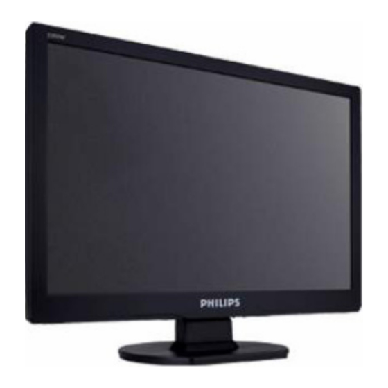
19" LCD Color Monitor
Service
Service
Service
Description
Table Of Contents.....................................................1
Revision List........................................................2
Important Safety Notice.............................................3
1. Monitor Specifications..............................................4
2. LCD Monitor Description..........................................6
3. Operation instructions.............................................7
3.1General Instructions........................................7
3.2 Control buttons...............................................7
3.3 Adjusting the Picture...............................................9
3.4 Connecting to the PC ........................................11
4. Input/Output Specification......................................12
4.1 Input Signal Connector.........................................12
4.2 Factory Preset Display Modes...............................12
4.3 Pixel Defect Policy..........................................13
4.4 Failure Mode Of Panel ....................................16
5. Block Diagram.................................................17
5.1 Software Flow Chart.............................................17
5.2 Electrical Block Diagram....................................19
6. Schematic Diagram.............................................21
ANY PERSON ATTEMPTING TO SERVICE THIS CHASSIS MUST FAMILIARIZE HIMSELF WITH THE
CHASSIS AND BE AWARE OF THE NECESSARY SAFETY PRECAUTIONS TO BE USED WHEN
SERVICING ELECTRONIC EQUIPMENT CONTAINING HIGH VOLTAGES.
CAUTION: USE A SEPARATE ISOLATION TRANSFOMER FOR THIS UNIT WHEN SERVICING
REFER TO BACK COVER FOR IMPORTANT SAFETY GUIDELINES
Copyright 2008 Philips Consumer Lifestyle
190VW9FB/97(1)
190VW9FB/97(2)
190VW9FB/94(1)
190VW9FB/94(2)
190VW9FB/62(1)
190VW9FB/27(2)
190VW9FB/27(1)
190VW9FB/75(2)
190VW9FB/05(1)
190VW9FB/93(2)
190VW9FB/00(1)
190VW9FB/62(2)
190VW9FB/75(1)
190VW9FB/78(1)
190VW9FB/93(1)
Page
Description
6.1 Main Board.................................................21
6.2 Power Board...............................................26
6.3 Key Board...................................................28
7. PCB Layout........................................................29
7.1 Main Board........................................................29
7.2 Power Board......................................................31
7.3 Key Board...................................................33
8. Wiring Diagram................................................34
9. Scalar Board Overview.....................................35
10. Mechanical Instructions......................................36
11.Trouble shooting...........................................41
12. Repair Flow Chart.........................................43
13. ISP Instructions....................................................49
14. DDC Instructions................................................57
15. White Balance, Luminance Adjustment.................65
16. Monitor Exploded View......................................67
17. Recommended & Spare Parts List.........................68
18. Different Parts List.............................................72
19. General Product Specification..........................76
SAFETY NOTICE
Subject to modification ○
Chassis: HUDSON 9
GB
Mar, 14, 2008
K
Page
3122 785 17860
Advertisement

Summary of Contents for Philips 190VW9FB/97
- Page 1 SERVICING ELECTRONIC EQUIPMENT CONTAINING HIGH VOLTAGES. CAUTION: USE A SEPARATE ISOLATION TRANSFOMER FOR THIS UNIT WHEN SERVICING REFER TO BACK COVER FOR IMPORTANT SAFETY GUIDELINES Copyright 2008 Philips Consumer Lifestyle Subject to modification ○ Mar, 14, 2008 3122 785 17860...
-
Page 2: Main Board
HUDSON 9 6. Schematic 6.1 Main Board 715G2904-1 TSUM16FWR SCHEMATIC XGA/SXGA LVDS OUTPUT DSUB_R+ DSUB_R+ VCC1.8 DSUB_R- DSUB_R- DSUB_G+ DSUB_G+ VCC3.3 DSUB_G- DSUB_G- VCC1.8 DSUB_SOG DSUB_SOG CMVCC DSUB_B+ DSUB_B+ DSUB_5V DSUB_B- DSUB_B- VCC3.3 CMVCC1 DSUB_H DSUB_H CMVCC1 DSUB_V DSUB_V DSUB_5V DDC1_SDA DDC1_SDA CMVCC... - Page 3 HUDSON 9 Input H_Sync R101 0R05 1/10W 5% R102 100R 1/16W 5% DSUB_H V_Sync R103 100R 1/16W 5% FB102 DSUB_V C101 R104 VGA_B+ CN101 B3 DSUB_B+ VCC3.3 R105 R106 C102 C103 BEAD 100R 1/16W 5% C101 A7 2K2 1/16W 5% 2K2 1/16W 5% 0.047uF C102 A4...
- Page 4 HUDSON 9 Scalar AVDD VDDP VDDC CN401 G1 VCC3.3 VDDP AVDD FB401 CN402 G7 C401 C3 U401 VCC3.3 C403 A9 300OHM C404 A9 VCTRL VCTRL C403 C404 C406 B9 LVA3P C407 B9 0.1uF/16V 0.1uF/16V DSUB_R+ RIN0P LVA3M C408 C1 DSUB_R- RIN0M PA[0..1] C409 D10...
- Page 5 HUDSON 9 Output PANEL_VCC CN403 PA[0..1] PB[0..9] PA[0..1] PB[0..9] CN403 A5 C419 C2 C420 A4 R434 C420 C421 C3 PA[4..9] PA[4..9] FB402 C3 330 OHM 1/4W 0.1uF/16V Q404 C2 Q405 C3 R433 C2 R434 A4 R435 C1 R436 C2 CMVCC AO3401L CMVCC R433...
- Page 6 HUDSON 9 Power Due to LG doen't request PC'99 Function. CN404 B1 C422 D6 D401 R458 C423 B7 C425 B3 0Ohm 1/16W C426 D5 C427 D7 ESD_VCC 2 C428 D5 OTHER BAV99 C432 B7 DSUB_5V D401 A2 CMVCC D402 B2 DSUB_5V 2 FB403 C6 Q406 B4...
-
Page 7: Power Board
HUDSON 9 6.2 Power Board 715G2824-I Power 100 OHM 1/4W R918 FB904 L904 +16V 100 OHM 1/4W R919 3.5uH C912 BEAD BD901 0.001uF R946 ZD902 100 OHM 1/4W R920 150OHM2W RLZ18B KBP208G C917 C918 680uF25V 680uF25V FB902 80OHM T901 Q903 R943 POWER X'FMR PMBS3904... - Page 8 HUDSON 9 Inverter +16V R805 100R 1/10W 5% ON/OFF D801 1N4148W Q805 CN801 PT801 CN801 A7 CN802 A7 POWER X'FMR C819 CN803 C7 CN804 C7 R806 100R 1/8W 68pF/3KV ZD802 C816 C801 B3 C802 B3 RLZ5.6B 22pF/6KV C803 C1 C804 C1 ZD803 D802 1N4148W C805 C2...
- Page 9 HUDSON 9 6.3 Key Board 715G3016-1 LED_RED# LED_GRN# LED001 CN001 R001 4.3K OHM 1% 1/8W LBADC1 R002 2.4K OHM 1% 1/8W LBADC2 DC_POWERON R003 910R 1/8W LED_GRN# LED_RED# R004 4.3K OHM 1% 1/8W C001 C002 C003 C004 C005 R005 2.4K OHM 1% 1/8W NC/0.001uF NC/0.001uF NC/0.001uF...
-
Page 10: Pcb Layout
HUDSON 9 7. PCB Layout 7.1 Main Board 715G2904-1 C101 FB101 B2 R418 C428 C102 FB102 B2 R419 R405 C103 FB103 B2 R420 SEN4 C104 FB401 B2 R421 C429 C105 FB402 A2 R424 R406 C106 FB403 A1 R425 U102 C107 FDT2 R426 C432... - Page 11 HUDSON 9...
- Page 12 HUDSON 9 7.2 Power Board 715G2824-I BD901 D3 J821 BD901A D3 J823 BD901B D3 J824 C604 J825 C812 J826 C816 J829 C817 J830 C819 J831 C820 J832 C821 J833 C822 J834 C824 J835 C900 J836 C901 J837 C902 J838 C903 J901 C905 J902...
- Page 13 HUDSON 9 C601 R818 D805 R926 C602 R819 D806 R927 C603 R820 D807 R930 C606 R821 D808 R935 C608 R822 D809 R938 C609 R823 D903 R939 C610 R824 FB902 C3 R940 C611 R825 IC801 B2 R942 C612 R826 IC901 C3 R943 C613 R827...
- Page 14 HUDSON 9 7.3 Key Board 715G3016-1 CN001 A3 GND1 GND2 LED001 A2 SW001 A1 SW002 A2 SW003 A1 SW004 A2 SW005 A3 C001 C002 C003 C004 C005 C006 C007 C008 C009 C010 R001 R002 R003 R004 R005 R007 ZD001 A1 ZD002 A3 ZD003 A1 ZD004 A2...
-
Page 15: Wiring Diagram
HUDSON 9 8. Wiring Diagram Panel 89G179E30N576 FFC Cable 30 Pin CN403 CN902 CN802 CN801 Power Board Main Board CN404 TSUM1PFR-LF U401 CN804 CN401 AC IN CN803 CN101 CN901 D-SUB 6 Pin Key Board CN001...


Need help?
Do you have a question about the 190VW9FB/97 and is the answer not in the manual?
Questions and answers