Table of Contents
Advertisement
Quick Links
Advertisement
Table of Contents

Related Manuals for Brama BR-30SSGG


Summary of Contents for Brama BR-30SSGG
- Page 1 A P R O U D H E R I T A G E O F E X P E R I E N C E & Q U A L I T Y BR-30SSGG BR-36SSGG B r a m a 3 0 ” F r e e s t a n d i n g...
-
Page 2: Table Of Contents
Table of Contents SAFETY AND WARNINGS ............................4 OTHER SAFETY TIPS ............................6 FEATURES: ............................... 8 LIST OF COMPONENTS LEGEND ........................10 GAS SUPPLY REQUIREMENTS ........................10 SAFETY TIPS FOR GAS OPERATION......................11 DIMENSIONS AND CLEARANCES .......................11 ELECTRIC POWER SUPPLY REQUIREMENTS ..................16 ELECTRIC GROUNDING INSTRUCTIONS ....................17 AFTER INSTALLATION ..........................18 FIRST USE ................................18 COOKTOP SAFETY GUIDELINES ........................20... - Page 3 SAVE THESE INSTRUCTIONS Welcome Thank you for purchasing your Brama indoor range. We appreciate your business and we recommend that you read this entire User’s Manual before operating your new appliance for the first time.
-
Page 4: Safety And Warnings
SAFETY AND WARNINGS Before you start Make sure that the anti-tip of the range has been properly installed. • Find the model and serial numbers on the CSA label in the bottom right-hand • corner of the backboard. Note these numbers down for future reference in the space provided in section ‘Warranty and service’. - Page 5 TIPPING HAZARD All ranges can tip and cause injuries to adults and children. To prevent tipping, install the anti-tip device supplied with your range. Follow all installation instructions. Even after the safety device is installed, do not step, lean or sit on the oven door or place any heavy objects on it.
-
Page 6: Other Safety Tips
POISONING HAZARD • Never cover any slots, holes or passages in the oven bottom or cover an entire rack or the oven floor with materials such as aluminum foil. Doing so blocks airflow through the oven and may cause carbon monoxide poisoning. - Page 7 OTHER SAFETY TIPS Cont. Don’t wear lose clothing that could catch fire Do not reach for items over the stove when it is lit Loose-fitting or hanging garments should never be Be careful when reaching for items stored in cabinets worn while using the appliance.
-
Page 8: Features
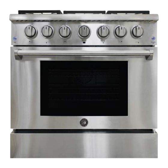
Do not let pot holder touch hot surface areas Do not use a towel or other bulky cloth. BR-30SSGG - BRAMA 30” FREESTANDING GAS RANGE FEATURES: • Convection • Dual Burner •... - Page 9 BR-36SSGG - BRAMA 36” FREESTANDING GAS RANGE FEATURES: • 36 Inch Freestanding Gas Range • Convection • Infrared Broil Burner • Dual Burners • Continuous Grates • 6 Sealed Burners • Automatic Re-Ignition • Stainless Steel Drip Pan • 5.2 cu. ft. Capacity •...
-
Page 10: List Of Components Legend
LIST OF COMPONENTS LEGEND GAS SUPPLY REQUIREMENTS Installation of this range must conform with local codes, or in the absence of local codes, with national Fuel Gas Code ANSIZ223.1 / NFPA 54. In Canada, installation must conform to the current natural Gas Installation /code, CAN 1-1.1-M81 and with local codes where applicable. -
Page 11: Safety Tips For Gas Operation
This range has been design-certified according to ANSIZ21.1a, latest edition. READING LP in W.C. NG (Natural GAS) in W.C. Maximum Gas 13.0 10.0 Pressure Appliance Regulator 10.0 Setting for Outlet Pressure SAFETY TIPS FOR GAS OPERATION • Keep appliance area clear and free from combustible materials, gasoline, and other flammable vapors. - Page 12 • The minimum distance from the side of the range above the counter top to combustible sidewalls must be at least 10 inches. DIMENSIONS FOR 30” RANGE (BR-30SSGG) The maximum depth of cabinets installed above cooking tops should be 13 in (330mm).
- Page 13 30” GAS RANGE CLEARANCE (BR-30SSGG) DIMENSIONS FOR 36” RANGE (BR-36SSGG) The maximum depth of cabinets installed above cooking tops should be 13 in (330mm). 1 7 6 2 1 S o u t h S u s a n a R o a d , R a n c h o D o m i n g u e z , C a l i f o r n i a 9 0 2 2 1...
- Page 14 36” GAS RANGE CLEARANCE (BR-36SSGG) TOP HOOD & CABINET SPECIFICATIONS Condition Minimum Clearance Allowed Clearance between the top of the cooking surface and 35” the bottom of an unprotected wood or metal cabinet. Clearance between the top of the cooking surface and the bottom wood or metal cabinet that is protected by not less than: 1/4-inch-thick flame-retardant millboard covered...
- Page 15 TOP HOOD & CABINET SPECIFICATIONS Cont. 1 7 6 2 1 S o u t h S u s a n a R o a d , R a n c h o D o m i n g u e z , C a l i f o r n i a 9 0 2 2 1 i n f o @ v i n o t e m p .
-
Page 16: Electric Power Supply Requirements
ELECTRIC POWER SUPPLY REQUIREMENTS Your range must be electrically grounded in accordance with local codes or, in the absence of local codes, in accordance with the National Electrical Code (ANSI/NFPA 70, latest edition). In Canada, electrical grounding must be in accordance with the current CSA C22.1 Canadian Electrical Code Part 1 and/or local codes. -
Page 17: Electric Grounding Instructions
ELECTRIC GROUNDING INSTRUCTIONS This indoor gas cooking appliance is equipped with a three-prong (grounding) plug for your protection against shock hazard and should be plugged directly into a properly grounded three- pronged receptacle. Where a standard two-prong wall receptacle is encountered, it is the responsibility and obligation of the customer to have it replaced with a properly grounded three-prong wall receptacle. -
Page 18: After Installation
AFTER INSTALLATION 1. Check ignition of cooktop burners. 2. Check ignition of oven burner. 3. Visually check tubular burner (oven burner) re-ignition to be sure both rows of burner ports are relighting each time. 4. Check for gas leaks at all gas connections (using a gas detector, never a flame). 5. - Page 19 Hold the front of both sides of the shelf firmly and keep it in horizontal. Put the shelf on the slot horizontally Lift the front about 15°upward till the tag of the shelf clear the safety stop of the side rack.
-
Page 20: Cooktop Safety Guidelines
COOKTOP SAFETY GUIDELINES There are dual burners have the same low turn-down setting (SIM) for gentle simmering (620 BTU/hr.). Use the SIM setting for melting chocolate and butter, cooking rice and delicate sauces, simmering soups and stews, and keeping cooked food hot. •... - Page 21 SURFACE BURNER IGNITION To light the top burners, push and turn the appropriate control knob counter clockwise to the “HI” position. You will hear a clicking noise – the sound of the electric spark igniting the burner. Once burner ignition has been achieved, then turn the burner control knob to adjust the desired heat setting.
- Page 22 POWER FAILURE If the gas does not ignite within four seconds, turn off the valve and allow at least five minutes for any gas to dissipate. Repeat the lighting procedure. If the power fails, it is not capable of being safely placed in operation and user that no attempt should be made to operate during power failure.
- Page 23 OVEN BURNER USE To light the oven burner, push and turn the appropriate control knob counter clockwise to the (150℉~500℉)position. You will hear a clicking noise – the sound of the electric spark igniting the burner. Once burner ignition has been achieved, then turn the burner control knob to adjust the desired heat setting.
-
Page 24: Oven Cooking Guidelines
OVEN COOKING GUIDELINES • Do not block the ducts on the rear of the range when cooking in the oven. It is important that the flow of warm air from the oven and fresh air into the oven burner never be interrupted. - Page 25 Convection Bake The oven convection fan circulates and distributes the heat in the oven for faster and even cooking. Convection cooking allows you to bake more items on multiple racks. TO BAKE USING THE CONVECTION FAN: Position the oven bottom cover and the oven shelves before using oven. Remove any unused shelves and baking utensils from the oven.
-
Page 26: Broiler Operation
Convection Defrost With temperature control off, a motorized fan in the rear of the oven circulates air. The fan accelerates natural defrosting of the food without heat. To avoid illness and food waste, do not allow defrost food to remain in the oven for more than two hours without being cooked. Defrosting To thaw uncooked frozen food, set the oven temperature to 100-150°F . - Page 27 To Broil Broil one side until the food is browned; turn and cook on the second side. Season and serve. Always pull the rack out to the “stop” position before turning or removing food. Setting Broil The “Oven” selector knob controls the Broil feature. When broiling, heat radiates downward from the oven broiler for even coverage.
-
Page 28: Cleaning Instructions
For the models with Griddle Before Using the Griddle Clean the griddle thoroughly with warm, soapy water to remove dust or any protective coating. Rinse with clean water and wipe off to dry with soft, clean, lint-free cloth. A stainless-steel cover when the griddle is not being used is provided. Please note that the cover must be removed before turning the griddle on. - Page 29 • Try using any cleaner on a small area first, to ensure it does not stain. • See the pages following this chart for instructions on removing and replacing various parts of the range for cleaning or maintenance. • To help you identify any parts, see illustrations in section ‘Introduction’ and after this cleaning chart.
- Page 30 Cleaning Side Racks Pre-soak any stubborn, burnt-on soiling, then clean with a solution of mild detergent and hot water and wipe dry with a microfiber cloth. Alternatively, clean these in the dishwasher. Cleaning Oven Shelves To remove stubborn or ‘baked-on’ soiling, scrub with a dampened, soap-filled, non- metal, non-abrasive pad, then wipe dry.
-
Page 31: Replacing The Burner Parts
Cleaning Stainless Steel Surfaces • Do not use any cleaning product with chlorine bleach. • Do not use a steel wool pad; it will scratch the surface. • Use a hot, damp cloth with a mild detergent. • Use a clean, hot, damp cloth to remove soap. Dry with a dry, clean cloth. REPLACING THE BURNER PARTS This diagram shows how to replace the burner parts. -
Page 32: Removing And Replacing The Oven Door
REMOVING AND REPLACING THE OVEN DOOR • Do not lift the oven door by its handle. Doing so may damage the door. • Make sure the oven and the door are cool before you begin to remove the door. • Before removing the door, make sure there is a large enough clear, protected surface in the kitchen to rest the door on. - Page 33 REPLACING THE OVEN DOOR 1. Hold the door firmly in an 3. Open the door fully as shown, approximately open position. 2. Insert the hinge tongues into the slots 4. Fully close the levers on the left and right making sure that the notches on both hinges, as shown, then close the door.
- Page 34 REPLACING THE OVEN LIGHT BULB When replacing bulbs, release the glass cover on the lamp holder first, and then remove the bulb to replace new light bulb. W W W . V I N O T E M P . C O M...
-
Page 35: Troubleshooting Guide
TROUBLESHOOTING GUIDE If you can’t find an answer to your problem in the chart below, or if the problem cannot be fixed, you will need technical help. Contact your Authorized Service Center or Customer Care. Problem Probable Causes What To Do COOKTOP Some burners will not light. - Page 36 Problem Possible Causes What To Do OVEN The oven doesn’t work (no No power supply (oven light and Check that the circuit breaker heating). halos do not come on either). hasn’t tripped and there is no power outage in your area. If No gas supply (gas ovens).
-
Page 37: Exhibit A Correct Position For Dual Burner
EXHIBIT A Correct Position for Dual Burner Here’s the procedure to check the condition for our current burner design. The procedure helps the electrode to sense the flame correctly. 1. Make sure the Burner Design is correct. Our current design for the burner is having the electrode on the left side (10 o’clock) and cross-over on the right side (2 o’clock). -
Page 38: Exhibit B How To Install Knobs And Handles
KNOB Your 30” unit has Your 30” unit has Your 30” unit has of these knobs of these knobs of these knobs (BR-30SSGG) (BR-30SSGG) (BR-30SSGG) Your 36” unit has Your 36” unit has Your 36” unit has of these knobs... - Page 39 BR-30SSGG BR-36SSGG 4. Your range might have a KD handle that needs to be installed. Please Follow up the following procedures for the oven door handle installation 4.1 Check your Installation Kits for Door Handles Your range has: 2 Handle Holders, 1 Installation Wrench 4.2 Connect door handle holders to each side of the handle...
- Page 40 Your range has: 1 Handle 4.3 Lay the door handle against to the oven door and fit it on the connection part, and use the wrench to get the door handle holder tight; 4.4 Use the wrench to tighten the door handle holders. W W W .
- Page 41 Warranty Brama warranty is one year from date of purchase. 1 7 6 2 1 S o u t h S u s a n a R o a d , R a n c h o D o m i n g u e z , C a l i f o r n i a 9 0 2 2 1...
-
Page 42: Terms Of Sale And Warranty
TERMS OF SALE AND WARRANTY Cancellation or Fees Terms: Shipping/Delivery fees are the responsibility of the Purchaser. Seller is not responsible for the carrier’s missed/Non delivery for any reason. Delivery is curbside. Optional upgrades in delivery service is an additional fee. If upgraded delivery service cannot be performed properly, Purchaser agrees to accept delivery curbside and the difference in upgraded cost will not be refunded. - Page 43 Il Romanzo units: Warranty 90 (ninety) days. Replacement part 12 (twelve) months from the date of sale. Brama: 1 year warranty from date of purchase. Non-New Units (Scratch & Dent/Refurbished/Floor Models), warranty for compressor units is 90 days from your dated invoice and 30 days for thermoelectric units (parts for function only, not cosmetic defects).
- Page 44 OF SALE Vinotemp (and its brands Element, Wine Mate, Cellar Tec, Apex Wine Racks, Epicureanist Il Romanzo, Brama(“Seller”) and the person of the entity that acquires these goods from Seller (“Purchaser”) hereby fully aggress to the following terms and conditions of the sale: 1.
-
Page 45: Service & Important Notice
SERVICE & IMPORTANT NOTICE Upon receipt and inspection of unit, the supply cord must be replaced if it is damaged. Contact our customer service at 1-800-777-8466 or info@vinotemp.com. The manufacturer has a policy of continuous improvement on its products and reserves the right to change materials and specifications without notice.
Need help?
Do you have a question about the BR-30SSGG and is the answer not in the manual?
Questions and answers
Oven slow to light off and produces an objectionable odor (not natural gas odor) during operation. Is this an indication that the hot surface ignitor needs tube replaced?