Advertisement
Quick Links
Advertisement

Related Manuals for airria AIRRIA-MU1000-0-075

Summary of Contents for airria AIRRIA-MU1000-0-075
- Page 1 INSTALLATION MANUAL Decentralized ventilation system AIRRIA-MU1000-0-075 AIRRIA...
- Page 2 1. Extract the AHU out of the casing Put the unit on its side on a table. Place the face towards you, and the two holes of the back downwards. Push each side of the face until the end of the spring. ...
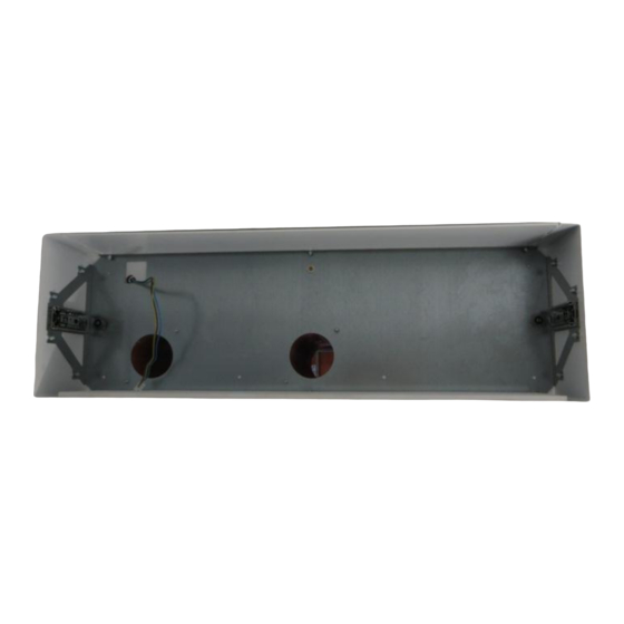
- Page 3 Trace the two circles, using the holes as pattern Figure 3 : Air circulation holes Determine the center, using the supplied cardboard circle Trace the supply cable output Figure 4 : Alimentation output...
-
Page 4: Supply Cable
Take off the screw and the casing. Figure 5 : Casing taking off 3. Make the holes 4. Supply cable Place the supply cable at the level of the intended output. Let the cable have 50cm extra length. Figure 6 : Alimentation wire v1.2... - Page 5 5. Place the empty casing on the wall Place the casing facing the holes. Make the supply cable enter the casing via the intended hole. Put the first screw. Level up. Put the remaining screws. Figure 7 : Casing installation 6.
- Page 6 Put a compression joint on each tube support Figure 10 : silicon joint Put each support in a 90mm duct. Figure 11 : Fixation of the support on the duct Place a 90mm duct in each orifice. Pay attention so the ducts exceed the exterior side by 5 Figure 12 : Installation of the duct v1.2...
- Page 7 The fouled air duct (on the right while being inside) has to be inclined towards the outside (at least 1,5% slope). Figure 13 : Duct inclination Figure 14 : Duct fixation Use foam or silicon to make sure everything between the hole and the ducts is airtight ...
- Page 8 Turn the AHU and place a 80 mm diameter duct and about 30 cm long on the viciated air exit. The length (about 30cm) must always be shorter than the wall thickness La longueur (30 cm environ) devant toujours être plus faible que l’épaisseur du mur ...
- Page 9 Slide the AHU into the casing and push until the end of the spring. Figure 18 : Fixation AHU / Casing Figure 19 : Fixation AHU / Casing Push again on each side of the face to unlock the AHU. Figure 20 : Fixation of the front face Figure 21 : Fixation of the front face ...
- Page 10 Turn on the AHU. Measure the in situ flows. Close the AHU Figure 24 : Wall AHU placed v1.2...
Need help?
Do you have a question about the AIRRIA-MU1000-0-075 and is the answer not in the manual?
Questions and answers