
Related Manuals for Next Wave CNC SHARK RS1000 PRO


Summary of Contents for Next Wave CNC SHARK RS1000 PRO
- Page 1 RS1000 PRO Assembly & Quick Start Manual © 2022 Next Wave CNC - All Rights Reserved...
- Page 3 Thank you for purchasing an RS1000 Pro router system set of plate levelers that allow you to precisely level the from Next Wave CNC! The RS1000 Pro opens up a world plate with your router table surface. The Plate fits most of creative possibilities for your ideas and designs.
- Page 4 This warranty is void if the RS1000 Pro or any portion of it is modified without the prior written permission from Next Wave CNC, or if the machine is located or has been used outside of the country where the machine was purchased.
- Page 5 For easy reference and record keeping, enter your RS1000 Pro information at right. To lo- cate the information, refer to the page 12. Next Wave CNC, LLC, 600 W. Boundary St., Perrysburg, Ohio 43551 Main Office Phone (419) 318-4822 info@nextwaveCNC.com...
-
Page 6: Table Of Contents
CONTENTS Assemble Your Shark RS1000 Pro Getting Started ........16 Machine Overview ........5 Zero Calibrate the Fence ...... 17 Assembly Overview ........6 Zero Calibrate the Bit ......18 Mounting the Positioner ......7 Pendant Guide to Setup and Apps Attaching the Fence ....... 8 ...21... -
Page 7: Machine Overview
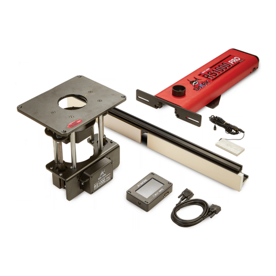
Machine Overview Before assembling and using your RS1000 Pro, we strongly recommend viewing the series of unboxing vid- eos with detailed instructions at See the Assembly Overview illustration below to get https://www.nextwavecnc.com/rs1000-pro familiar with all of the parts of your RS1000 Pro. Optional miter gauge guide rail Fence positioner mounts Optional miter guage... -
Page 8: Assembly Overview
Assembly Overview The miter gauge, an optional accessory, provides a solid There are three primary components included with your foundation for the workpiece during the routing opera- RS1000 Pro. The router lift attached to the router table tion. The T-tracks on the miter gauge fence allow easy insert plate controls the height of the lift in increments attachment of clamps, stop blocks, and other accesso- of 0.XXX”... -
Page 9: Mounting The Positioner
Mark centerline on router table before install- ing the fence positioner Front edge of table Mark and drill ⁄ holes for mount- 4” 4” ing the positioner using the includ- ed hardware Center mounting plate on table top Rear edge of router table Mounting the Positioner The RS1000 Pro fence fits onto a mechanical assembly router tabletop with a pencil. -
Page 10: Attaching The Fence
Fasten fence faces with studded knobs into threaded inserts on back of fence face Center fence on positioner and fasten with studded knobs Attach the Fence After the positioner is secure, you’ll attach the fence next. attach the two MDF faces to the fence also secure the The fence assembly consists of the aluminum extrusion, fence to the positioner. -
Page 11: Router Lift Installation
Router Lift Assembly Router lift assembly The router lift assembly moves the router up and down to adjust the height of the router bit above the table. The two motors at the bottom of the lift con- nect to the router plate. The phenolic router plate supports the lift and secures it to the router table. -
Page 12: Connecting The Cables
Hooking up the Cables IMPORTANT NOTE: DO NOT PLUG POWER The cable ends from the positioner and Pendant will only SUPPLY into your 115V outlet until all of the fit in one of the two plugs on the controller. After making control cables are connected or you may the connections, tighten the thumbscrews to secure the damage the electronics. -
Page 13: Install Optional Miter Gauge Fence
Adding the Optional Miter Gauge The optional miter gauge is an ideal upgrade for your on the fence, then tighten the cap screws just until the RS1000 Pro. It allows unprecedented positioning and rail is secure. control of the workpiece during routing operations. Install the sliding bracket by first removing the two knobs The T-tracks on the miter gauge fence make it easy to at- from the bearing block. -
Page 14: Machine & Pendant Registration
Use the number keys on the Pendant to enter your Unlock (Access) Code. Press Sub- mit. This unlocks the Pendant. Your SHARK RS1000 Pro is now unlocked and ready to use. Unlock the Pendant by entering the unlock code you received upon registration. -
Page 15: Safety Tips
Our 10 Golden Rules for Safety 1. Read and follow all safety and operating instructions before using the RS1000 Pro. 2. Understand that the fence and lift move during use, and take the time to orient yourself to the RS1000 Pro and the workflow steps. 3. -
Page 16: Quick Guide
Quick Guide to Basic RS1000 PRO Movement Keys Lift and Fence position fields – These two fields show the current location of the fence and height of the router bit relative to the zero position. Pressing a position button opens an edit screen where you can change the value. - Page 17 Quick Guide to Basic Pendant Function Keys Inch/Metric – Pressing Jog Speed – Press this Step Key – Press to change this key switches the units key to change the jog the distance the fence or lift between imperial, fraction- speed of the fence and lift incrementally moves when al, and metric.
-
Page 18: Getting Started
Getting Started with the RS1000 Pro To unlock the potential of the RS1000 Pro and access its that needs to be entered. The first step in the calibration extensive library of joint making apps it is necessary to sequence is to enter the bit diameter. Open the Bit Diam- first create a “baseline”... -
Page 19: Zero Calibrate The Fence
Calibrate Bit to Fence Before using the RS1000 Pro, the fence and router bit need to be calibrated with the touch plate accessory, as illustrat- ed in Figure 1. Calibrating the fence establishes the zero Fence point for the fence in relation to the router bit. To begin the fence calibration process, plug the cable on the touch plate into the Pendant. -
Page 20: Zero Calibrate The Bit
With a proper connection, the screen will turn red, as The screen turns red to indicate movement (Figure 8). in Figure 6. Place the touch plate against the fence as When the touch plate contacts the router bit, the fence shown in Figure 1. - Page 21 Calibrate Bit to Table Fence Similar to the fence calibration on the previous pages, you’ll need to calibrate the router bit height using the touch plate (Figure 1). This establishes the zero height of the bit. To begin the router bit calibration process, make sure the Touch plate touch plate cable is connected to the Pendant (Figure 1).
- Page 22 With a proper connection, the screen will turn red, as in The screen turns red to indicate bit movement (Figure 8). Figure 6. Place the touch plate flat on the router table When the touch plate contacts the router bit, the bit will over the opening in the insert plate, as shown in Figure 1.
-
Page 23: Pendant Guide To Setup And Apps
Pendant Guide to Setup and Apps On the main screen of the Pendant, pressing the Position d. Fence Position Display Field: Pressing this opens fields open a numeric keypad. The left Position field sets up the Lift Position Edit Screen (Figure 2) e. -
Page 24: Setup Menu
Setup Menu Setup Menu Screen: Pressing the Setup button on the Main Control screen displays the Setup screen. The Setup menu contains options for controlling specific RS1000 Pro functions. Press a menu item to open the settings screen for that option. To return to the Main Control Screen, press the X in the upper right corner. - Page 25 Reference Bit: This option establishes the zero, and a value of 2 references from the back edge of or home, of the fence position relative to the bit’s the router bit. The reference position you choose is geometry using a value of 0, 1, or 2. Use a value up to you and, in most cases, is a personal prefer- of 0 to reference from the center of the bit.
- Page 26 Custom Step: The custom step function allows Touch Plate Thickness: The Touch Plate Thick- you to add a custom increment to the step key in ness option sets the thickness of the touch plate. the main window (see page 21). Clear Faves Memory: This option clears all previ- Factory Restore: Use this to restore the default ous favorite setups from Faves menu.
-
Page 27: Apps Quick Start Guide
Apps Quick Start Guide Your RS1000 Pro comes preprogrammed with a the system does all the math and moves the fence number of apps that make it easier to complete a and router lift as needed to complete the task. The variety of useful functions. -
Page 28: Dado Cut
Dado Cut One of the most common joints in woodworking is a dado joint. The RS1000 Pro includes an app specifically for cutting dadoes and grooves. Select Dado Cut from the Apps menu, then Press To Run. At the screen shown in Fig- ure 1, enter the dado parameters, including router bit width, dado width, and offset from the edge of the workpiece. - Page 29 Dado Cut Setup continued Select Start Offset to set the location of the dado from the edge Enter the offset distance on the numeric keypad and press OK. of the workpiece. Press the value button on the upper right. Next, select Dado Width to set the width of the dado. Press Enter the dado width on the numeric keypad and press OK.
- Page 30 Run Dado Cuts With the parameters set, press Run Dado Cut, then Press to Acknowledge the instruction regarding the orientation of the Run to start the app. workpiece by pressing OK. The screen displays the location of the router lift and fence. This screen appears when the lift, fence, or both are moving Press OK to move them to their starting positions.
-
Page 31: Maintenance
To remove these bits of sawdust, fold a small piece of paper and run it around the perimeter of the Updates are available via the Ready2Update-Firmware app, which can be download from your Next Wave CNC screen as shown. User Account. Or visit https://portal.nextwavecnc.com/ TIP - To reduce problems from dust, mount the Pendant on Portal/Login. - Page 32 RS1000 Pro Assembly & Quick Start Manual Version: 10/06/2022...
Need help?
Do you have a question about the SHARK RS1000 PRO and is the answer not in the manual?
Questions and answers