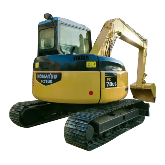
Komatsu PC78US-6 Operation & Maintenance Manual
Hydraulic excavator
Hide thumbs
Also See for PC78US-6:
- Operation & maintenance manual (285 pages) ,
- Shop manual (51 pages)
Table of Contents
Advertisement
Quick Links
Operation & Maintenance
Operation & Maintenance
Operation & Maintenance
Operation & Maintenance
Manual
Manual
Manual
Manual
This material is proprietary to Komatsu Utility Division and is not to be reproduced, used, or disclosed
except in accordance with written authorization from Komatsu America International Company.
It is out policy to improve our products whenever it is possible and practical to do so. We reserve the right to
make changes or improvements at any time without incurring any obligation to install such changes on
products sold previously.
Due to this continuous program of research and development, revisions may be made to this publication. It
is recommended that customers contact their distributor for information on the latest revision.
December 2001
PC78US
HYDRAULIC EXCAVATOR
SERIAL NUMBERS
PC78US - 4562
Copyright 2001 Komatsu
DataKom Publishing Corporation
SEAM044601T
-6
and up
Advertisement
Chapters
Table of Contents

Related Manuals for Komatsu PC78US-6


Summary of Contents for Komatsu PC78US-6
- Page 1 SERIAL NUMBERS and up This material is proprietary to Komatsu Utility Division and is not to be reproduced, used, or disclosed except in accordance with written authorization from Komatsu America International Company. It is out policy to improve our products whenever it is possible and practical to do so. We reserve the right to make changes or improvements at any time without incurring any obligation to install such changes on products sold previously.
- Page 2 1 - 1...
-
Page 3: Foreword
Keep this manual at the storage location for the Operation and Maintenance Manual given below, and have all personnel read it periodically. If this manual has been lost or has become dirty and cannot be read, request a replacement manual immediately from Komatsu or your Komatsu distributor. - Page 4 FOREWORD FOREWORD 1 - 3...
- Page 5 FOREWORD FOREWORD 1 - 4...
-
Page 6: Safety Information
FOREWORD SAFETY INFORMATION SAFETY INFORMATION To enable you to use this machine safely, safety precautions and labels are given in this manual and affixed to the machine to give explanations of situations involving potential hazards and of the methods of avoiding such situations. - Page 7 Continuing improvements in the design of this machine can lead to changes in detail which may not be reflected in this manual. Consult Komatsu or your Komatsu distributor for the latest available information of your machine or for questions regarding information in this manual.
-
Page 8: Introduction
FOREWORD INTRODUCTION INTRODUCTION This Komatsu machine is designed to be used mainly for the following work: Digging work Leveling work Ditching work Loading work Demolition work See the section "RECOMMENDED APPLICATIONS (PAGE 3-98)" for further details. DIRECTIONS OF MACHINE In this manual, the terms front, rear, left, and right refer to the travel direction as seen from the operator's cab when the operator's cab is facing the front and the sprocket is at the rear of the machine. -
Page 9: Product Information
FOREWORD PRODUCT INFORMATION PRODUCT INFORMATION When requesting service or ordering replacement parts, please inform your Komatsu distributor of the following items. MACHINE SERIAL NUMBER PLATE AND ITS LOCATION On the bottom right of the operator's cab ENGINE SERIAL NUMBER PLATE AND ITS LOCATION On the upper side of the engine cylinder head cover EPA: Environmental Protection Agency, U.S.A. -
Page 10: Service Meter Location
FOREWORD PRODUCT INFORMATION SERVICE METER LOCATION On top of the machine monitor YOUR MACHINE SERIAL NUMBERS AND DISTRIBUTOR Machine serial No. Engine serial No. Distributor name Address Service Personnel Phone/Fax 1 - 9... -
Page 11: Table Of Contents
FOREWORD CONTENTS CONTENTS FOREWORD FOREWORD SAFETY INFORMATION INTRODUCTION DIRECTIONS OF MACHINE PRODUCT INFORMATION MACHINE SERIAL NUMBER PLATE AND ITS LOCATION ENGINE SERIAL NUMBER PLATE AND ITS LOCATION SERVICE METER LOCATION YOUR MACHINE SERIAL NUMBERS AND DISTRIBUTOR SAFETY SAFETY INFORMATION WARNING LABELS AND PICTOGRAMS WARNING LABELS AND PICTOGRAMS - LOCATION WARNING LABELS AND PICTOGRAMS - ACTUAL SAFETY INFORMATION... - Page 12 FOREWORD CONTENTS GREASE PUMP HOLDER 3- 55 ASHTRAY 3- 55 FIRE EXTINGUISHER 3- 56 MACHINE OPERATIONS AND CONTROLS 3- 57 BEFORE STARTING ENGINE 3- 57 STARTING ENGINE 3- 73 AFTER STARTING ENGINE 3- 77 STOPPING THE ENGINE 3- 80 CHECK AFTER SHUT OFF ENGINE 3- 80 MACHINE OPERATION 3- 81...
- Page 13 FOREWORD CONTENTS WEAR PARTS LIST LUBRICANTS, FUEL AND COOLANT SPECIFICATIONS PROPER SELECTION TIGHTENING TORQUE SPECIFICATIONS 4- 12 TIGHTENING TORQUE LIST 4- 12 SAFETY CRITICAL PARTS 4- 13 SAFETY CRITICAL PARTS LIST 4- 13 MAINTENANCE SCHEDULE 4- 14 MAINTENANCE SCHEDULE CHART 4- 14 MAINTENANCE INTERVAL FOR HYDRAULIC BREAKER 4- 15...
- Page 14 2 - 1...
- Page 15 SAFETY SAFETY INFORMATION SAFETY INFORMATION WARNING LABELS AND PICTOGRAMS WARNING LABELS AND PICTOGRAMS - LOCATION WARNING LABELS AND PICTOGRAMS - ACTUAL SAFETY INFORMATION Safety rules 2- 11 If abnormalities are found 2- 11 Working wear and personal protective items 2- 11 Fire extinguisher and first aid kit 2- 11 Safety equipment...
-
Page 16: Safety
SAFETY SAFETY INFORMATION SAFETY MACHINE OPERATION 2- 19 STARTING ENGINE 2- 19 Checks before starting engine 2- 19 Safety rules for starting engine 2- 19 Starting engine in cold weather 2- 20 OPERATION 2- 21 Checks before operation 2- 21 Safety rules for changing machine directions 2- 21 Safety rules for traveling... -
Page 17: Warning Labels And Pictograms
If the labels are damaged, lost, or cannot be read properly, replace them with new ones. For details of the part numbers for the labels, see this manual or the actual label, and place an order with Komatsu distributor. 2 - 4... -
Page 18: Warning Labels And Pictograms - Location
SAFETY WARNING LABELS AND PICTOGRAMS WARNING LABELS AND PICTOGRAMS - LOCATION 2 - 5... -
Page 19: Warning Labels And Pictograms - Actual
SAFETY WARNING LABELS AND PICTOGRAMS WARNING LABELS AND PICTOGRAMS - ACTUAL (1) Precautions for operation, inspection and (2) Precautions for before operation (09802-03000) maintenance (09651-03001) (3) Warning for leaving operator's seat (09654-03001) (4) Warnings for high voltage (09801-03001) 2 - 6... - Page 20 SAFETY WARNING LABELS AND PICTOGRAMS (5) Precautions for operating pattern (6) Precautions for operating pattern (if equipped) Standard machine (09822-03000) Machine equipped with operating pattern selector valve (21W-98-44220) 2 - 7...
- Page 21 SAFETY WARNING LABELS AND PICTOGRAMS (7) Precautions for opening the window (8) Precautions for stowage (09803-03000) (09839-03000) (9) Precautions for broken or becomes dislodged to (10) Precautions when switching operating pattern the window (20U-98-21910) (22M-98-11180) (machines equipped with operating pattern selector valve) 2 - 8...
- Page 22 SAFETY WARNING LABELS AND PICTOGRAMS (11) Precautions for high-temperature cooling water (12) Precautions for high-temperature hydraulic oil (14X-98-11531) (09653-03001) (13) Precautions for high-temperature parts (14) Precautions for check and adjust track tension (09817-A0753) (09657-03003) 2 - 9...
- Page 23 SAFETY WARNING LABELS AND PICTOGRAMS (15) Precautions for handling electric wires (16) Precautions for opening engine hood (09808-03000) (09667-03001) (17) Prohibited to enter range of swing (09133-23000) (18) Precautions when handling battery (09664-30082) The safety labels, (1) through (5) and (7), are a single seal. In replacement, place an order for it with Part No. 22U-00-21290.
-
Page 24: Safety Information
SAFETY SAFETY INFORMATION SAFETY INFORMATION Safety Rules Only trained and authorized personnel can operate and maintain the machine. Follow all safety rules, precautions and instructions when operating or performing maintenance on the machine. If you are under the influence of alcohol or medication, your ability to safely operate or repair your machine may be severly impaired putting yourself and everyone else on your jobsite in danger. -
Page 25: Keep Machine Clean
SAFETY SAFETY INFORMATION Keep Machine Clean If water gets into the electrical system, there is a hazard that it will cause malfunctions or misoperation. Do not use water or steam to wash the electrical system (sensors, connectors). If inspection and maintenance is carried out when the machine is still dirty with mud or oil, there is a hazard that you will slip and fall, or that dirt or mud will get into your eyes. -
Page 26: Handrails And Steps
SAFETY SAFETY INFORMATION Handrails and Steps To prevent personal injury caused by slipping or falling off the machine, always do as follows. Use the handrails and steps marked by arrows in the diagram on the right when getting on or off the machine. To ensure safety, always face the machine and maintain three-point contact (both feet and one hand, or both hands and one foot) with the handrails and steps (including the track shoe) -
Page 27: Burn Prevention
SAFETY SAFETY INFORMATION Burn Prevention Hot coolant To prevent burns from hot water or steam spurting out when checking or draining the coolant, wait for the water to cool to a temperature where it is possible to touch the radiator cap by hand before starting the operation. -
Page 28: Action If Fire Occurs
The above recommendations assume that the conditions are for standard operations, but it may be necessary to add additional guards according to the operating conditions on the jobsite. Always contact your Komatsu distributor for advice. 2 - 15... -
Page 29: Attachment Installation
Any modification made without authorization from Komatsu can create hazards. Before making a modification, consult your Komatsu distributor. Komatsu will not be responsible for any injuries, accidents, product failures or other property damages resulting from modifications made without authorization from Komatsu. -
Page 30: Working On Loose Ground
SAFETY SAFETY INFORMATION Working on Loose Ground Avoid traveling or operating your machine too close to the edge of cliffs, overhangs, and deep ditches. The ground may be weak in such areas. If the ground should collapse under the weight or vibration of the machine, there is a hazard that the machine may fall or tip over. -
Page 31: Ventilation For Enclosed Area
Do not allow other persons to approach during the operation. Always observe the rules and regulations for the work site and environmental standards. This machine does not use asbestos, but there is a danger that imitation parts may contain asbestos, so always use genuine Komatsu parts. 2 - 18... -
Page 32: Safety Machine Operation
SAFETY SAFETY MACHINE OPERATION SAFETY MACHINE OPERATION STARTING ENGINE If there is a warning tag hanging from the work equipment control lever, do not start the engine or touch the levers . Checks Before Starting Engine Carry out the following checks before starting the engine at the beginning of the day's work. Remove all dirt from the surface of the window glass to ensure a good view. -
Page 33: Starting Engine In Cold Weather
SAFETY SAFETY MACHINE OPERATION Starting Engine in Cold Weather Carry out the warming-up operation thoroughly. If the machine is not thoroughly warmed up before the control levers are operated, the reaction of the machine will be slow, and this may lead to unexpected accidents. If the battery electrolyte is frozen, do not charge the battery or start the engine with a different power source. -
Page 34: Operation
SAFETY SAFETY MACHINE OPERATION OPERATION Checks Before Operation When carrying out the checks, move the machine to a wide area where there are no obstructions, and operate slowly. Do not allow anyone near the machine. Always fasten your seat belt. Check that the movement of the machine matches the display on the control pattern card. -
Page 35: Safety Rules For Traveling
SAFETY SAFETY MACHINE OPERATION Safety Rules for Traveling It is dangerous to drive too fast, or to start suddenly, stop suddenly, or to turn sharply. When traveling on level ground, keep the work equipment at a height of 40 to 50 cm (1.6 to 2.0 in) from the ground. When traveling on rough ground, travel at low speed and do not operate the steering suddenly. -
Page 36: Traveling On Slopes
SAFETY SAFETY MACHINE OPERATION Traveling on Slopes To prevent the machine from tipping over or slipping to the side, always do as follows. Keep the work equipment approx. 20 to 30 cm (8 to 12 in) above the ground. In case of emergency, lower the work equipment to the ground immediately to help stop the machine. -
Page 37: Operations On Slopes
SAFETY SAFETY MACHINE OPERATION Operations on Slopes When working on slopes, there is a hazard that the machine may lose its balance and turn over when the swing or work equipment are operated. This may lead to serious injury or property damage, so always provide a stable place when carrying out these operations, and operate carefully. -
Page 38: Operations On Snow
SAFETY SAFETY SAFETY MACHINE OPERATION SAFETY MACHINE OPERATION Do not carry out demolition work under the machine. There is a hazard that the machine may become unstable and tip over. When working on or from the top of buildings or other structures, check the strength and the structure before starting operations. -
Page 39: Parking Machine
SAFETY SAFETY MACHINE OPERATION Parking Machine Park the machine on firm, level ground. Select a place where there is no hazard of falling rocks or landslides, or of flooding if the land is low. Lower the work equipment completely to the ground. When leaving the machine, set safety lock lever (1) to the LOCK position, then stop the engine. -
Page 40: Transportation
SAFETY MACHINE OPERATION TRANSPORTATION The machine can be divided into parts for transportation, so when transportating the machine, please contact your Komatsu distributor to have the work carried out. Loading and Unloading When loading or unloading the machine, mistaken operation may bring the hazard of the machine tipping over or falling, so particular care is necessary. -
Page 41: Battery
SAFETY SAFETY MACHINE OPERATION BATTERY Battery Hazard Prevention Battery electrolyte contains sulphuric acid, and batteries generate flammable hydrogen gas, which may explode. Mistaken handling can lead to serious injury or fire. For this reason, always observe the following precautions. Do not use or charge the battery if the battery electrolyte level is below the LOWER LEVEL line. This may cause an explosion. -
Page 42: Starting Engine With Booster Cables
SAFETY SAFETY MACHINE OPERATION Starting Engine with Booster Cables If any mistake is made in the method of connecting the booster cables, it may cause the battery to explode, so always do as follows. When starting with a booster cable, carry out the starting operation with two workers (one worker sitting in the operator's seat and the other working with the battery). -
Page 43: Towing
SAFETY SAFETY MACHINE OPERATION TOWING Safety Rules for Towing Serious injury or death could result if a disabled machine is towed incorrectly or if there is a mistake in the selection or inspection of the wire rope. For towing, see "TOWING THE MACHINE (PAGE 3-121)". Always wear leather gloves when handling wire rope. -
Page 44: Lifting Objects With Bucket
SAFETY SAFETY MACHINE OPERATION LIFTING OBJECTS WITH BUCKET Safety Rules for Lifting Objects Do not carry out lifting work on slopes, soft ground, or other places where the machine is not stable. Use wire rope that conforms to the specified standard. Do not exceed the specified lifting load. -
Page 45: Safety Maintenance Information
SAFETY SAFETY MAINTENANCE INFORMATION SAFETY MAINTENANCE INFORMATION Warning Tag Always attach the "DO NOT OPERATE" warning tag to the work equipment control lever in the operator's cab to alert others that you are performing service or maintenance on the machine. Attach additional warning tags around the machine if necessary. -
Page 46: Two Workers For Maintenance When Engine Is Running
SAFETY SAFETY SAFETY MAINTENANCE INFORMATION SAFETY MAINTENANCE INFORMATION Set safety lock lever (1) to the LOCK position. Put blocks under the track to prevent the machine from moving. Two Workers for Maintenance when Engine is Running To prevent injury, do not carry out maintenance with the engine running. -
Page 47: Proper Tools
SAFETY SAFETY MAINTENANCE INFORMATION Proper Tools Use only tools suited to the task and be sure to use the tools correctly. Using damaged, low quality, faulty, makeshift tools or improper use of the tools could cause serious personal injury. Personnel Only authorized personnel can service and repair the machine. -
Page 48: When Using Hammer
If it is disassembled by mistake, the spring will fly out and cause serious injury. When it becomes necessary to disassemble it, ask your Komatsu distributor to do the work. 2 - 35... -
Page 49: Safety Rules For High-Pressure Oil
If any loose bolts are found, stop work and tighten to the specified torque. If any damaged hoses are found, stop operations immediately and contact your Komatsu distributor. Replace the hose if any of the following problems are found. -
Page 50: Compressed Air
SAFETY SAFETY MAINTENANCE INFORMATION Compressed Air When carrying out cleaning with compressed air, there is a hazard of serious injury caused by flying particles. When using compressed air to clean elements or the radiator, always wear safety goggles, dust mask, gloves, and other protective equipment. - Page 52 3 - 1...
-
Page 53: Machine View Illustrations
OPERATION MACHINE VIEW ILLUSTRATIONS MACHINE VIEW ILLUSTRATIONS OVERALL MACHINE VIEW (1) Bucket (8) Working lamp (2) Bucket cylinder (9) Sprocket (3) Arm (10) Track frame (4) Arm cylinder (11) Track shoe (5) Boom (12) Idler (6) Boom cylinder (13) Blade cylinder (7) Additional lamp (if equipped) (14) Blade 3 - 2... -
Page 54: Controls And Gauges
OPERATION MACHINE VIEW ILLUSTRATIONS CONTROLS AND GAUGES (1) Car radio (19) Alarm buzzer stop switch (2) Heater control panel (20) Emergency pump drive switch (3) Safety lock lever (21) Swing brake cancel switch (4) Left work equipment control lever (22) Travel speed selector switch (5) Swift deceleration switch (23) Working mode selector switch (6) Traveling accelerator pedal... -
Page 55: Detailed Controls And Gauges
OPERATION DETAILED CONTROLS AND GAUGES DETAILED CONTROLS AND GAUGES The following is an explanation of the devices needed for operating the machine. To carry out suitable operations correctly and safely, it is important to understand fully the methods of operating the equipment and the meanings of the displays. - Page 56 OPERATION DETAILED CONTROLS AND GAUGES Caution Monitors If the warning monitor flashes, check the problem point as soon as possible and carry out maintenance. Failure to repair the problem will lead to failure of the machine. These are items which need to be observed when the engine is running. If any abnormality occurs, the item needing immediate repair is display.
- Page 57 OPERATION DETAILED CONTROLS AND GAUGES Fuel Level Monitor This monitor (2) warns against the reduced fuel level in the fuel tank. When the remaining fuel reaches 30 liters (7.93 US gal) level, the fuel level monitor begins to flash. Then refill fuel without delay. 3 - 6...
- Page 58 OPERATION DETAILED CONTROLS AND GAUGES Emergency Monitors If the monitor flashes, stop the engine immediately or run at low idling, then inspect the problem point immediately and repair the problem. These are items which need to be observed when the engine is running. If there is any abnormality, the abnormal location on the monitor will lights up and the buzzer will second.
- Page 59 OPERATION DETAILED CONTROLS AND GAUGES Engine Oil Pressure Monitor If the engine lubricating pressure is below the normal value, this monitor (2) flashes. If it flashes, stop the engine, and check the oil level in the oil pan and lubricating system. REMARK This lamp will light up if the starting switch is turned ON when the engine is stopped, but this does not indicate any...
- Page 60 OPERATION DETAILED CONTROLS AND GAUGES Meter Display Portion Pilot Display Meter (1) Engine pre-heating monitor (3) Engine coolant temperature gauge (2) Swift deceleration monitor (4) Fuel gauge (5) Display (6) Service meter Pilot Display When the starting switch is ON, the pilot display lights up when the display items are functioning. Engine Pre-heating Monitor This monitor (1) indicates the pre-heating time required when starting the engine at an ambient temperature below 0 C (32 F).
- Page 61 OPERATION DETAILED CONTROLS AND GAUGES REMARK When the swift deceleration monitor is lights up, the engine speed remains at low idling even if the fuel control dial is operated. Gauges and Meter Engine Coolant Temperature Gauge This meter (3) shows the engine cooling water temperature. During normal operation, the lamp should light up in the green range (A).
- Page 62 OPERATION DETAILED CONTROLS AND GAUGES Display This monitor (5) serves to display failure contents, if any abnormality occurs on the machine. REMARK If the machine has a fault, error information appears while the starting switch is ON. The monitor flashes and displays all error information sequentially.
- Page 63 OPERATION DETAILED CONTROLS AND GAUGES Monitor Switches Portion (1) Working mode selector switch (3) Wiper switch (2) Travel speed selector switch (4) Window washer switch Working Mode Selector Switch This switch (1) is used to set the power and movement of the work equipment.
- Page 64 OPERATION DETAILED CONTROLS AND GAUGES Travel Speed Selector Switch When loading or unloading from a trailer, always travel at low speed. Never operate the travel speed selector switch during the loading or unloading operation. If the travel speed is switched between Hi and Lo when the machine is traveling, the machine may deviate to one side, even when traveling in a straight line.
- Page 65 OPERATION DETAILED CONTROLS AND GAUGES Window Washer Switch This switch (4) is kept continuously pressed, window washer fluid is sprayed out on the front glass. When the switch is released, the spray stops. If switch (4) is kept pressed when the wiper is stopped, the window washer fluid will spray out, and at the same time, the wiper will be actuated continuously.
-
Page 66: Switches
OPERATION DETAILED CONTROLS AND GAUGES SWITCHES (1) Starting switch (6) Alarm buzzer stop switch (2) Fuel control dial (7) Emergency pump drive switch (3) Swift deceleration switch (8) Swing brake cancel switch (4) Horn button (9) Room lamp switch (5) Lamp switch (10) Cigarette lighter Starting Switch This switch (1) is used to start or stop the engine. - Page 67 OPERATION OPERATION DETAILED CONTROLS AND GAUGES DETAILED CONTROLS AND GAUGES REMARK The engine does not start, if the safety lock lever is not in the LOCK position. Make sure first that the safety lock lever is in the LOCK position, and then move the engine starting switch. Fuel Control Dial This dial (2) is used to control engine speed and output.
- Page 68 OPERATION DETAILED CONTROLS AND GAUGES REMARK When fuel control dial is at the low idling position, the engine speed will not go down any lower even if this switch is pressed. If the engine speed does not rise, it is possible that this switch is ON. Lock at the swift deceleration monitor to check the condition of the switch.
- Page 69 OPERATION DETAILED CONTROLS AND GAUGES Pump Drive Emergency Switch NOTICE This switch is installed to make it possible to carry out operation temporarily if any abnormality should occur in the pump control system. It is not intended for permanent use. Repair the cause of the abnormality immediately. If this switch is depressed and moved to the EMERGENCY position by mistake, thereby engaging the machine in the work, while the machine is in normal condition, an "E02"...
- Page 70 OPERATION DETAILED CONTROLS AND GAUGES Room Lamp Switch NOTICE Be sure to switch the lamp to the OFF position after use. If the switch is left at the ON position, the battery will run down. This switch (9) is used to light up the room lamp. ON position: Lights up OFF position: Goes off REMARK...
-
Page 71: Control Levers And Pedals
OPERATION DETAILED CONTROLS AND GAUGES CONTROL LEVERS AND PEDALS (1) Safety lock lever (4) Blade control lever (2) Left work equipment control lever (5) Travel levers (machines with travel pedals) (3) Right work equipment control lever (6) Traveling accelerator pedal Safety Lock Lever When leaving the operator's cab, be sure to move the safety lock lever to the LOCK position. - Page 72 Work Equipment Control Lever The operating pattern is set to the standard operating pattern (ISO pattern). When changing the operating pattern, please contact your Komatsu distributor. The method of using operating patterns other than the ISO pattern is given in the ATTACHMENT AND OPTIONS section. Always read and understand the contents before operating the machine.
- Page 73 OPERATION DETAILED CONTROLS AND GAUGES Blade Control Lever This lever (4) is used to control the blade. (a): LOWER (b): RAISE Travel Levers Do not put your foot on the pedal unless the machine is traveling. If you leave your foot on the pedal and press it by mistake, the machine will move suddenly, and this may lead to a serious accident.
- Page 74 OPERATION DETAILED CONTROLS AND GAUGES Traveling Accelerator Pedal If the pedal (6) is depressed, the machine speed will increase. For details of the travel speed values, see "SPECIFICATIONS (PAGE 5-2)". REMARK The acceleration pedal works, when the travel speed shifting switch in the monitor panel is at low speed position (Lo lamp lights up).
-
Page 75: Sun Roof
OPERATION DETAILED CONTROLS AND GAUGES SUN ROOF When leaving the operator's compartment, set the safety lock lever securely to the LOCK position. If the control levers are not locked, and they are touched by mistake, this may lead to a serious accident. When opening or closing the roof hatch, carry out the operation on horizontal ground. -
Page 76: Windshield
OPERATION DETAILED CONTROLS AND GAUGES WINDSHIELD When opening or closing the front window, bottom window, or door, always set the safety lock lever to the LOCK position. If the control levers are not locked and they are touched by accident, this may lead to a serious accident. - Page 77 OPERATION OPERATION DETAILED CONTROLS AND GAUGES DETAILED CONTROLS AND GAUGES 5. Hold lower knob (C) with your left hand from inside the operator's cab, and with your right hand, grip top knob (D), pull it up, and push it against lock catch (E) at the rear of the cab securely to lock the window.
- Page 78 OPERATION DETAILED CONTROLS AND GAUGES Closing When closing the window, lower it slowly and be careful not to get your hand caught. 1. Stop the machine on level ground, lower the work equipment completely to the ground, then stop the engine. 2.
- Page 79 OPERATION OPERATION DETAILED CONTROLS AND GAUGES DETAILED CONTROLS AND GAUGES 5. When the bottom of the window reaches the top of the bottom window, push the top of the window to the front to push it against left and right lock catches (G) and engage the lock. 6.
- Page 80 OPERATION DETAILED CONTROLS AND GAUGES Removing Lower Windshield 1. Open the front window, then hold grip (A), pull up, and remove the bottom window. 2. After removing the bottom window, stow it on the inside left of the operator's cab, then lock securely in position with lock lever (B).
- Page 81 OPERATION OPERATION DETAILED CONTROLS AND GAUGES DETAILED CONTROLS AND GAUGES 2) After inserting into groove (D) of the bottom frame rubber and rear frame rubber (A), push the bottom window against lock base (C). NOTICE If the window rise up on lock base (C) or is not in contact with lock lever (B), and it is attempted to engage the lock by force, there is danger that the glass may break.
-
Page 82: Sliding Door
OPERATION DETAILED CONTROLS AND GAUGES SLIDING DOOR Be sure to check that the sliding door is locked in position both when it is open and when it is closed. Always stop the machine on level ground when opening or closing the door. - Page 83 OPERATION OPERATION DETAILED CONTROLS AND GAUGES DETAILED CONTROLS AND GAUGES To escape from the operator's cab, use hammer (A) to break the glass and escape through the window. 3 - 32...
-
Page 84: Cap With Lock
OPERATION DETAILED CONTROLS AND GAUGES CAP WITH LOCK Use the starting key to open and close the locks on the caps and covers. For details of the locations of the caps and covers with locks, see "LOCKING (PAGE 3-103)". Insert the key as far as it will go, then turn it. If the key is turned before it is inserted fully, it may break. -
Page 85: Engine Hood
OPERATION DETAILED CONTROLS AND GAUGES ENGINE HOOD Never attempt to climb on the engine hood. There is the danger that you may slip off. When carrying out inspection and maintenance inside the engine hood, always use the hood support lever to hold the engine hood open. -
Page 86: Mud Cover
OPERATION DETAILED CONTROLS AND GAUGES MUD COVER Never attempt to climb on the cover. There is the danger that you may slip off. When carrying out inspection and maintenance inside the cover, always use the cover support lever to hold the cover open. NOTICE Always keep the hood locked except when opening it. -
Page 87: Battery Inspection Cover
OPERATION DETAILED CONTROLS AND GAUGES BATTERY INSPECTION COVER When carrying out inspection and maintenance inside the cover, always use the cover support lever to hold the cover open. NOTICE Always keep the door locked except when opening it. 1. Release lock (1) of door. (For details see "Opening and Closing Covers with Lock (PAGE 3-33)".) 2. -
Page 88: Fuse
OPERATION DETAILED CONTROLS AND GAUGES FUSE NOTICE Before replacing a fuse, be sure to turn off the starting switch. The fuses protect the electrical equipment and wiring from burning out. If the fuse becomes corroded, or white powder can be seen, or the fuse is loose in the fuse holder, replace the fuse. Replace the fuse with another of the same capacity. -
Page 89: Fusiblelink
AUXILIARY ELECTRIC POWER NOTICE When installing electrical not supplied by Komatsu, use 24 V specifications with a maximum of 600 W (equivalent to 25 A). If equipment is to be installed with a capacity greater than this, please contact your Komatsu distributor. -
Page 90: Heater And Defrostar Controls
OPERATION DETAILED CONTROLS AND GAUGES HEATER AND DEFROSTAR CONTROLS Heater and Defroster Control Panel (1) Vent selector switch (4) Air flow selector switch (2) FRESH/RECIRC selector switch (5) OFF switch (3) Temperature control switch (6) Defroster selector lever Vent Selector Switch (Sending Air to Face) If this switch (1) is pressed, the air from the heater is all directed to the face. - Page 91 OPERATION DETAILED CONTROLS AND GAUGES Vent Selector Switch (Sending Air to Face and Feet) If this switch (1) is pressed, the air from the heater is directed to the face and feet. Vent Selector Switch (Sending Air to feet) If this switch (1) is pressed, the air from the heater is all directed to the feet.
- Page 92 OPERATION DETAILED CONTROLS AND GAUGES FRESH/RECIRC Selector Switch (Fresh) When switch (2) is pressed, fresh air is taken into the cab during heating. This position is used to bring in clean fresh air into the cab or to remove the mist from the cab windows. FRESH/RECIRC Selector Switch (Recirclate) When switch (2) is pressed, the air inside the cab is recalculated and no fresh air is taken in from outside.
- Page 93 OPERATION DETAILED CONTROLS AND GAUGES Temperature Control Switch (Warm) Use switch (3) to increase the temperature. Press this switch to increase the temperature of the air sent from the heater. The more times the switch is pressed, the upper the blowing wind temperature becomes, as the indicator light moves to the right.
- Page 94 OPERATION DETAILED CONTROLS AND GAUGES Off Switch Switch (5) is used to stop operation of heater function. Defroster Selector Lever Switch (6) is used to remove the mist from the front glass during cold or rainy weather. Selector lever to front: To defroster (open) Selector lever to rear: Closed The defroster can be used when the vent selector switch is set to send air to the face or to the face and the feet.
-
Page 95: Air Conditioner Controls
OPERATION DETAILED CONTROLS AND GAUGES AIR CONDITIONER CONTROLS (If equipped) Air Conditioner Control Panel (1) Vent selector switch (5) Air conditioner switch (2) FRESH/RECIRC selector switch (6) Off switch (3) Temperature control switch (7) Defroster selector lever (4) Air flow selector switch Vent Selector Switch (Air Flow to Upper Part of Body) If this switch (1) is pressed, the air from the air conditioner is all directed to the face. - Page 96 OPERATION DETAILED CONTROLS AND GAUGES Vent Selector Switch (ir Flow to Upper Part of Body and foot) If this switch (1) is pressed, the air from the air conditioner is directed to the face and feet. Vent Selector Switch (Air Flow to Foot) If switch (1) is pressed, the air from the air conditioner is all directed to the feet.
- Page 97 OPERATION DETAILED CONTROLS AND GAUGES Air Circulation Selector Switch (External Air Circulation) When switch (2) is pressed, fresh air is taken into the cab during heating or cooling. This position is used to bring in clean fresh air into the cab or to remove the mist from the cab windows.
- Page 98 OPERATION DETAILED CONTROLS AND GAUGES Temperature Control Switch (Heating) Use switch (3) to increase the temperature. Press this switch to increase the temperature of the air sent from the air conditioner. The more times the switch is pressed, the lower the blowing wind temperature becomes, as the indicator light moves to the "H".
- Page 99 OPERATION DETAILED CONTROLS AND GAUGES Air Conditioner Switch Switch (5) is used to switch the air conditioner functions ON/OFF. Off Switch Switch (6) is used to stop operation of the fan. Defroster Selector Lever Switch (7) is used to remove the mist from the front glass during cold or rainy weather.
- Page 100 OPERATION DETAILED CONTROLS AND GAUGES Air Conditioner Maintenance When carrying out inspection and maintenance of a machine equipped with air conditioner, see "INITIAL 250 HOURS MAINTENANCE (ONLY AFTER THE FIRST 250 HOURS) (PAGE 4-16)". 3 - 49...
-
Page 101: Radio
OPERATION DETAILED CONTROLS AND GAUGES RADIO (If equipped) Control Panel (1) Power switch/volume control (SW-VOLUME) and (5) Manual tuning button (TUNING) Balance (Pull BAL) Knob (6) Preset station buttons (1, 2, 3, 4, 5, 6) (2) Tone control knob (TONE) (7) Display (3) FM/AM selection button (AM/FM) (8) Time reset button... - Page 102 OPERATION DETAILED CONTROLS AND GAUGES Tone Control Knob (TONE) Turn the knob(2) to adjust the tone as follows. Turn CLOCKWISE to emphasize the high sounds. Turn COUNTERCLOCKWISE to suppress the high sounds. FM/AM Selection Button (AM/FM) Press this button(3) and select the desired band. Each time the button is pressed, it switches AM C FM C AM ...
- Page 103 OPERATION DETAILED CONTROLS AND GAUGES Preset Station Buttons (1, 2, 3, 4, 5, 6) If these buttons(6) are set to the frequency of the desired broadcasting station, the station can be selected at a touch. For details of the method of presetting, see "Preset Station Buttons (PAGE 3-53)".
- Page 104 OPERATION DETAILED CONTROLS AND GAUGES Controls Of Radio Preset Station Buttons 1. Press power switch (1) and display the frequency on display (7). 2. Turn the tuning button(5) (manual, auto) to adjust to the desired frequency. 3. Select a preset button to use for recording the frequency setting, and keep that button pressed for at least 1.5 seconds.
- Page 105 OPERATION DETAILED CONTROLS AND GAUGES Setting Correct Time 1. Press display selector button (4) to display the time. After 5 seconds, the display will return to the frequency display and the time cannot be corrected. If this happens, press display selector button (4) again. 2.
-
Page 106: Operation Manual Storage
OPERATION DETAILED CONTROLS AND GAUGES OPERATION MANUAL STORAGE A magazine box is provided on the left side of the operator's seat for safekeeping the operation and maintenance manual and oil chart. Always keep the Operation and Maintenance Manual in this pocket so that it is possible to read it at any time. -
Page 107: Fire Extinguisher
OPERATION DETAILED CONTROLS AND GAUGES FIRE EXTINGUISHER (If equipped) A fire extinguisher is prepared at the rear part inside the operator's cab. The directions are described on the nameplate affixed to it. Just in case, carefully read and grasp them beforehand. 3 - 56... -
Page 108: Machine Operations And Controls
Remove any flammable materials from around the battery or engine muffler, or other high temperature engine parts. Leakage of fuel or oil will cause the machine to catch fire. Check carefully, and sure to repair any abnormalities, or please contact your Komatsu distributor. If the machine is at an angle, make it horizontal before checking. - Page 109 Check that there is no abnormality in the seat belt or mounting clamps. If there is any damage, replace with new parts. 11. Check bucket with hook (if equipped) for damage. Check that there is no damage to the hook, guide, or hook mount. If any abnormality is found, please contact your Komatsu distributor for repair. 3 - 58...
- Page 110 OPERATION MACHINE OPERATIONS AND CONTROLS Checks Before Starting Always carry out the items of the checks in this section before starting the engine each day. Cooling System Coolant Level - Check/Add Do not open the radiator cap unless necessary. When checking the coolant, always wait for the engine to cool down and check the sub tank.
- Page 111 OPERATION MACHINE OPERATIONS AND CONTROLS Engine Crankcase Oil Level - Check/Add The parts and oil are at high temperature immediately after the engine is stopped, and may cause serious burns. Wait for the temperature to go down before starting the operation. 1.
- Page 112 OPERATION MACHINE OPERATIONS AND CONTROLS Fuel Level - Check/Refill When adding fuel, never spill the fuel or let it overflow. It will cause fire. If any fuel has spilled, wipe it up completely. If fuel has spilled over soil or sand, remove that soil or sand. Fuel is highly flammable and dangerous.
- Page 113 OPERATION MACHINE OPERATIONS AND CONTROLS Hydraulic Oil Level - Check/Add The parts and oil are at high temperature after the engine is stopped, and may cause burns.Wait for the temperature to go down before starting the work. When removing the oil filler cap, turn it slowly to release the internal pressure, then remove it. 1.
- Page 114 OPERATION OPERATION MACHINE OPERATIONS AND CONTROLS MACHINE OPERATIONS AND CONTROLS 2. Open battery inspection cover (1) and check sight gauge (G) for the oil level. If it stays within the following range, it is regarded as appropriate. In Machine Condition A: Within the range a In Machine Condition B: Within the range b NOTICE Do not add oil above the H line.
- Page 115 OPERATION MACHINE OPERATIONS AND CONTROLS Air Cleaner Dust Indicator - Check 1. Open the engine hood and check that the red piston is not showing in dust indicator (1). 2. If the red piston has appeared, clean or replace the element immediately.
- Page 116 Horn Function - Check 1. Turn the starting switch to the ON position. 2. Confirm that the horn sounds immediately when the horn button is pressed. If the horn does not sound, please contact your Komatsu distributor for repair. 3 - 65...
- Page 117 OPERATION MACHINE OPERATIONS AND CONTROLS Adjustment Adjust the seat position before starting operations or after changing the operator. Adjust the seat so that the control levers and switchis can be operated freely and easily with the operator back against the backrest.
- Page 118 OPERATION MACHINE OPERATIONS AND CONTROLS Rearview Mirrors Adjust the angle of the mirrors so that the area to the bottom rear of the operator's seat (the area hidden by the engine hood) can be seen clearly. 3 - 67...
- Page 119 OPERATION MACHINE OPERATIONS AND CONTROLS Seat Belt Before fastening the seat belt, check that there is no abnormality in the securing brackets or belt. If there is any wear or damage, replace. Even if there appears to be no abnormality in the seat belt, replace the seat belt once every 3 years. The date of manufacture is woven on the reverse side of the belt.
- Page 120 OPERATION MACHINE OPERATIONS AND CONTROLS Seat Belt Adjustment Shortening Pull the free end on the tongue side. Lengthening Pull the seat belt with a tongue in the direction perpendicular to the tongue. 3 - 69...
- Page 121 OPERATION MACHINE OPERATIONS AND CONTROLS Wind-in Type Seat Belt (If equipped) Before fitting the seat belt, check that there is no abnormality in the belt mount bracket or mounting belt. If it is worn or damaged, replace the seat belt. Even if no abnormality can be seen in the belt, replace the seat belt every 3 years.
- Page 122 If the monitors or gauges do not light up or the buzzer does not sound, there is probably a blown bulb or disconnection, so please contact your Komatsu distributor for repair. After approx. 3 seconds, the following monitors and gauges will remain on and the others will go out.
- Page 123 2) Press horn switch (11) to confirm that the horn will sound. 3) Press lamp switch (12) to turn on the working lamps. If it does not light up, there is probably a blown bulb or disconnection, so please contact your Komatsu distributor for repairs. 3 - 72...
-
Page 124: Starting Engine
OPERATION MACHINE OPERATIONS AND CONTROLS STARTING ENGINE Normal Starting Check that there are no persons or obstacles in the surrounding area, then sound the horn and start the engine. Exhaust gas is toxic. When starting the engine in confined spaces, be particularly careful to ensure good ventilation. NOTICE Do not try to start the engine with the fuel adjustment dial set near the full engine rotation. - Page 125 OPERATION OPERATION MACHINE OPERATIONS AND CONTROLS MACHINE OPERATIONS AND CONTROLS 4. When the engine start, release the key in the starting switch (3). The key will return automatically to the ON position. 5. Keep the engine idling for the initial 15 seconds right after it has been started, and do not operate any control lever or the fuel adjustment dial during that time.
- Page 126 OPERATION MACHINE OPERATIONS AND CONTROLS Starting Engine In Cold Weather Check that there are no persons or obstacles in the surrounding area, then sound the horn and start the engine. Never use starting aid fluids as they may cause explosions. Exhaust gas is toxic.
- Page 127 OPERATION OPERATION MACHINE OPERATIONS AND CONTROLS MACHINE OPERATIONS AND CONTROLS 4. Hold the key in starting switch (3) at the HEAT position, and check that pre-heating monitor (4) lights up. After about 30 seconds, pre-heating monitor (4) will flash 10 seconds to indicate that pre-heating is finished.
-
Page 128: After Starting Engine
Breaking-In The New Machine Your Komatsu machine has been thoroughly adjusted and tested before shipment. However, operating the machine under severe conditions at the beginning can adversely affect the performance and shorten the machine life. Be sure to breaking-in the machine for the initial 100 hours (as indicated by the service meter). - Page 129 OPERATION MACHINE OPERATIONS AND CONTROLS Warming-Up Operation NOTICE When the hydraulic oil is at a low temperature, do not carry out operations or move the lever suddenly. Always carry out the warming-up operation. This will help to extend the machine life. Do not suddenly accelerate the engine before the warming-up operation is completed.
- Page 130 Display (13): OUT 6. Check that there is no abnormal exhaust gas color, noise, or vibration. If any abnormality is found, contact your Komatsu distributor. 7. Move safety lock lever (2) to the LOCK position and confirm that none of the operations for the control levers, work equipment, blade (if a blade is installed), swing and travel can be made.
-
Page 131: Stopping The Engine
OPERATION MACHINE OPERATIONS AND CONTROLS STOPPING THE ENGINE NOTICE If the engine is stopped abruptly, service life of component parts of the engine may be considerably reduced. Hence do not stop the engine abruptly except in an emergency. If the engine has overheated, do not try to stop it abruptly but run it at medium speed to allow it to cool down gradually, and then stop it. -
Page 132: Machine Operation
OPERATION MACHINE OPERATIONS AND CONTROLS MACHINE OPERATION Before operating the steering levers, check the direction of the track frame. If the sprocket is at the front, the operation of the travel levers is reversed. When moving off, check that the area around the machine is safe, and sound the horn before moving. Do not allow anyone in the area around the machine. - Page 133 ("Lo" lamp lights up). For details if the speed, see "SPECIFICATIONS (PAGE 5-2)". 5. Check that the travel alarm sounds. If the alarm dose not sounds, please contact your Komatsu distributor for repairs. 3 - 82...
- Page 134 ("Lo" lamp lights up). For details if the speed, see "SPECIFICATIONS (PAGE 5-2)". 5. Check that the travel alarm sounds. If the alarm dose not sounds, please contact your Komatsu distributor for repairs. 3 - 83...
- Page 135 OPERATION MACHINE OPERATIONS AND CONTROLS Stopping Machine Avoid stopping suddenly. Give yourself ample room when stopping. Put the left and right travel levers (1) in the neutral position, then stop the machine. 3 - 84...
-
Page 136: Steering The Machine
OPERATION MACHINE OPERATIONS AND CONTROLS STEERING THE MACHINE Steering Before operating the travel control levers, check the direction of the track frame (i.e. position of the sprocket) first. If the sprocket is at the front, the machine moves in the reverse direction to the operation of the travel lever. Use the travel levers to change direction. - Page 137 OPERATION MACHINE OPERATIONS AND CONTROLS Changing Direction of the Machine When turning to the left: If the left travel lever is returned to the neutral position, the machine will turn to the left. REMARK When turning to the right, operate the right travel lever in the same way.
-
Page 138: Swinging
OPERATION MACHINE OPERATIONS AND CONTROLS SWINGING When operating the swing, check that the area around the machine is safe. 1. Operate left work equipment control lever (1) to swing the upper structure. 2. When not using the swing, set left work equipment control lever (1) to the N position. -
Page 139: Work Equipment Controls And Operations
OPERATION MACHINE OPERATIONS AND CONTROLS WORK EQUIPMENT CONTROLS AND OPERATIONS For operation patterns other than the standard one (ISO pattern), refer to the chapter of ATTACHMENTS AND OPTIONS in this manual. Use the control levers to operate the work equipment. Note that when the levers are released, they return to the HOLD position and the work equipment is held in that position. - Page 140 OPERATION OPERATION MACHINE OPERATIONS AND CONTROLS MACHINE OPERATIONS AND CONTROLS Bucket control Move the right work equipment control lever to the left or right to operate the bucket. Blade control (blade specification) Move the lever on the right side of the operator's seat to the front or rear to operate the blade.
-
Page 141: Working Mode
OPERATION MACHINE OPERATIONS AND CONTROLS WORKING MODE By using the working mode selector switch to select a working mode that matches the operating condition, it is possible to carry out operations efficiently. Use the following procedure to make effective use of each working mode. Active Mode (for heavy-duty work) and E Mode (for work focusing on fuel consumption ratio) are alternated, every time the working mode switch is depressed. -
Page 142: Prohibited Operations
OPERATION MACHINE OPERATIONS AND CONTROLS PROHIBITED OPERATIONS Do not attempt to operate the work equipment control lever, while the machine is traveling. Operations Using Swing Force Do not use the swing force to compact soil or break objects. This is not only dangerous, but will also markedly reduce the life of the machine. - Page 143 OPERATION MACHINE OPERATIONS AND CONTROLS Operations Using Bucket Dropping Force Do not use the dropping force of the machine for digging, or use the dropping force of the bucket as a pickaxe, breaker, or pile driver. This will markedly reduce the life of the machine. Operations Using Machine Dropping Force Do not use the dropping force of the machine for digging.
-
Page 144: General Operation Information
OPERATION MACHINE OPERATIONS AND CONTROLS GENERAL OPERATION INFORMATION Traveling Traveling over boulders, tree stumps, or other obstacles will cause a big shock to the chassis (and in particular to the tracks), and this will cause damage to the machine. For this reason, always remove any obstacles or travel around them, or take other steps to avoid traveling over such obstacles as far as possible. - Page 145 OPERATION MACHINE OPERATIONS AND CONTROLS Blade During Backhoe Operations When carrying out deep digging operations with the blade at the front, be careful not to the boom cylinder hit the blade. Always position the blade at the back unless it is needed at the front. Permissible Water Depth When driving the machine out of water, if the angle of the machine exceeds 15 , the rear of the upper structure will go under water, and water will be...
-
Page 146: Traveling On Slopes
OPERATION MACHINE OPERATIONS AND CONTROLS TRAVELING ON SLOPES Turning or operating the work equipment when working on slopes may cause the machine to lose it balance and turn over, so avoid such operations. It is particularly dangerous to swing downhill when the bucket is loaded. If such operations have to be carried out, pile soil to make a platform on the slope so that the machine can be kept horizontal when operating. - Page 147 OPERATION OPERATION MACHINE OPERATIONS AND CONTROLS MACHINE OPERATIONS AND CONTROLS 2. When traveling up a steep hill of more than 15 , set the work equipment to the posture shown in the diagram on the right. Traveling Downhill Put the travel lever in the neutral position. This will cause the brake to be automatically applied. Engine Stopped on Slope If the engine stops when traveling uphill, move the travel levers to the neutral position, stop the machine, then start the engine again.
-
Page 148: Escape From Mud
OPERATION MACHINE OPERATIONS AND CONTROLS ESCAPE FROM MUD Always operate carefully to avoid getting affixed in mud. If the machine does get affixed in mud, do as follows to get the machine out. Stuck One Side Of Track NOTICE When using the boom or arm to raise the machine, always have the bottom of the bucket in contact with the ground. -
Page 149: Recommended Applications
OPERATION MACHINE OPERATIONS AND CONTROLS RECOMMENDED APPLICATIONS In addition to the following, it is possible to further increase the range of applications by using various attachments. Backhoe Work A backhoe is suitable for excavating at a position lower than the machine. - Page 150 OPERATION MACHINE OPERATIONS AND CONTROLS Loading Work In places where the swing angle is small, work efficiency can be enhanced by locating the dump truck in a place easily visible to the operator. Loading dump trucks is easier and the loading capacity is greater if the hydraulic excavator loads from the rear of the dump truck rather than from the side.
-
Page 151: Bucket Replacement And Inversion
OPERATION MACHINE OPERATIONS AND CONTROLS BUCKET REPLACEMENT AND INVERSION When pins are knocked in with a hammer, pieces of metal may fly and cause serious injury. When carrying out this operation, always wear goggles, hard hat, gloves, and other protective equipment. When the bucket is removed, place it in a stable condition. - Page 152 OPERATION MACHINE OPERATIONS AND CONTROLS Inversion When reversing a bucket, there is the danger that the bucket tooth tip overruns the normal trajectory and interferes with the cab, thus causing a serious trouble. Pay good attention to the work when reversing a bucket so that the bucket and the cab may not interfere with each other.
-
Page 153: Parking Machine
OPERATION MACHINE OPERATIONS AND CONTROLS PARKING MACHINE Park the machine on the firm, level ground. Avoid parking the machine on slopes. If it is unavoidably necessary to park the machine on a slope, put blocks under the tracks and dig the work equipment into the ground surface to stop the machine from moving. -
Page 154: Machine Inspection After Daily Work
OPERATION OPERATION MACHINE OPERATIONS AND CONTROLS MACHINE OPERATIONS AND CONTROLS 5. Set safety lock lever (2) in the LOCK position. MACHINE INSPECTION AFTER DAILY WORK Check the engine water temperature (1), engine oil pressure (2), and fuel level (3) on the machine monitor. LOCKING Always look the following places. -
Page 155: Road Liners And Rubber Shoes
OPERATION MACHINE OPERATIONS AND CONTROLS ROAD LINERS AND RUBBER SHOES (Machine equipped with road liner or rubber shoe) Road Liners And Rubber Shoes Information Road liners and rubber shoes have excellent properties that are not found in steel shoes. However, if they are used in the same way as steel shoes, full use cannot be made of their advantages. - Page 156 OPERATION MACHINE OPERATIONS AND CONTROLS Using Road Liners And Rubber Shoes Prohibited Works Do not carry out the following types of work. Carrying out operations and steering on crushed rock, extremely rough hard rock, steel beams, scrap iron, or near the edges of steel plates will cause damage to the road liners and rubber shoes.
- Page 157 OPERATION MACHINE OPERATIONS AND CONTROLS Always maintain the rubber shoes at the proper tension to prevent them from coming off. If the tension is low, the rubber shoes will come off under the following conditions. Even if the tension is correct, be extremely careful when carrying out operations. 1.
- Page 158 OPERATION MACHINE OPERATIONS AND CONTROLS Mechanism of rubber shoe coming off track 1) When traveling over an obstacle, a gap is formed between the track roller and the rubber shoe. In this condition, the rubber shoe may come off. 2) Furthermore, if the machine travels in reverse, a gap is formed between the track roller, idler, and rubber shoe.
- Page 159 OPERATION OPERATION MACHINE OPERATIONS AND CONTROLS MACHINE OPERATIONS AND CONTROLS If the machine is turned in this condition, the rubber shoe will come off. 3 - 108...
-
Page 160: Transportation
OPERATION TRANSPORTATION TRANSPORTATION When transporting the machine, observe all related laws and regulations, and be careful to assure safety. TRANSPORTATION PROCEDURE As a basic rule, transport the machine by trailer. Select the trailer to match the weight and dimensions given in "SPECIFICATIONS (PAGE 5-2)". Note that the value for the weight and transportation dimensions given in SPECIFICATIONS may differ according to the type of shoe or type of arm or other attachments. - Page 161 OPERATION TRANSPORTATION Loading 1. Perform loading and unloading on firm, level ground only. Maintain a safe distance from the edge of a road. 2. Properly apply the brakes on the trailer and put blocks under the tires to ensure that the trailer does not move. Make the slope of the ramps a maximum of 15 .
- Page 162 OPERATION OPERATION TRANSPORTATION TRANSPORTATION 7. Do not the operate the accelerator pedal. 8. Stop the machine at the specified place, then swing the upper structure slowly 180 . 9. Stop the machine at the specified position on the trailer. 3 - 111...
- Page 163 OPERATION TRANSPORTATION Securing Machine After placing the machine on the specified position of the trailer, secureit according to the following procedure. NOTICE To prevent damage to the bucket cylinder during transportation, fit a wooden block at one end of the bucket cylinder to prevent it from touching the floor.
- Page 164 OPERATION TRANSPORTATION Unloading 1. Perform loading and unloading on firm, level ground only. Maintain a safe distance from the edge of a road. 2. Properly apply the brakes on the trailer and put blocks under the tires to ensure that the trailer does not move. Before moving onto the ramps, make sure that the machine is positioned in a straight line with the ramps and that the centerline of the machine matches that of the trailer.
- Page 165 OPERATION OPERATION TRANSPORTATION TRANSPORTATION 9. Raise the work equipment, align the direction of travel with the ramp, and travel slowly. Lower the work equipment as far as possible without causing interference. When on the ramps, operate only the travel lever. Do not operate any other lever or pedal.
-
Page 166: Lifting Machine
The lifting procedure applies to machines with standard specifications. The method of lifting differs according to the attachments and options actually installed. In such cases, please contact your Komatsu distributor for information. When lifting the machine, carry out the operation on flat ground as follows. - Page 167 OPERATION OPERATION TRANSPORTATION TRANSPORTATION 6. Pass wire ropes between the 1st and 2nd track rollers from the front and between the 1st and 2nd track rollers from the rear. NOTICE Do not attempt to lift up the machine by hanging a wire rope to the bracket that is provided for fastening the machine in transportation.
-
Page 168: Cold Weather Operation
When changing the coolant or when handling coolant containing antifreeze that has been drained when repairing the radiator, please contact your Komatsu distributor. Antifreeze is toxic, so do not let it flow into drainage ditches or spray it on to the ground surface. - Page 169 OPERATION COLD WEATHER OPERATION Battery The battery generates flammable gas, so do not bring fire or sparks near the battery. Battery electrolyte is dangerous. If it gets in your eyes or on your skin, wash it off with large amount of water, and consult a doctor.
-
Page 170: After Daily Work Completion
OPERATION COLD WEATHER OPERATION AFTER DAILY WORK COMPLETION Performing idle-running of the tracks is dangerous, so stay well away from the tracks. To prevent mud, water, or the undercarriage from freezing and making it impossible for the machine to move on the following morning, always observe the following precautions. -
Page 171: Long Term Storage
Rotate the tracks. AFTER STORAGE NOTICE If the machine is to be used when the monthly rust prevention operation has not been carried out, please contact your Komatsu distributor. When using the machine after long-term storage, do as follows before using it. -
Page 172: Troubles And Actions
OPERATION TROUBLES AND ACTIONS TROUBLES AND ACTIONS RUNNING OUT OF FUEL When starting after running out of fuel, fill with fuel and bleed the air from the fuel system before starting. For details of bleeding the air, see "Air Bleeding (PAGE 4-59)". PHENOMENA THAT ARE NOT FAILURES Note that the following phenomena are not failures: When the arm control lever is operated to the IN position and the... -
Page 173: Severe Job Condition
OPERATION TROUBLES AND ACTIONS SEVERE JOB CONDITION When carrying out digging operations in water, if the work equipment mounting pin goes into the water, carry out greasing every time the operation is carried out. For heavy-duty operations and deep digging, carry out greasing of the work equipment mounting pins every time before operation. - Page 174 OPERATION TROUBLES AND ACTIONS Battery Removal And Installation Removal of Battery 1. Open up dust cover (1) and battery inspection cover (2). 2. Loosen bolts (3) to remove sheet (4) installed above the battery. 3. Disconnect cable (5) from the negative (-) terminal (grounding side) first.
- Page 175 OPERATION TROUBLES AND ACTIONS Battery Charges When charging the battery, if the battery is not handled correctly, there is a hazard that the battery may explode. Always follow the instructions of "DISCHARGED BATTERY (PAGE 3-122)" and the instruction manual accompanying the charger, and do as follows. Set the voltage of the charger to match the voltage of the battery to be charged.
- Page 176 OPERATION TROUBLES AND ACTIONS NOTICE The size of the booster cable and clip should be suitable for the battery size. The battery of the normal machine must be the same capacity as that of the engine to be started. The starting system for this machine uses 24 V. For the normal machine, also use a 24 V battery. Check the cables and clips for damage or corrosion.
-
Page 177: How To Lower Work Equipment When Engine Stops Due To Abnormality
OPERATION TROUBLES AND ACTIONS HOW TO LOWER WORK EQUIPMENT WHEN ENGINE STOPS DUE TO ABNORMALITY Before loosening the plug, thoroughly check safety under the work equipment and the blade. Never allow anyone to go under the work equipment or the blade. While the work equipment is descending, keep holding the plug with a tool, so that the descent may be stopped any moment. -
Page 178: Other Trouble
TROUBLES AND ACTIONS OTHER TROUBLE Electrical System ( ): Always contact your Komatsu distributor when dealing with these items. In cases of abnormalities or causes which are not listed below, please contact your Komatsu distributor for repairs. Problem Main causes... - Page 179 OPERATION TROUBLES AND ACTIONS Chassis ( ): Always contact your Komatsu distributor when dealing with these items. In cases of abnormalities or causes which are not listed below, please contact your Komatsu distributor for repairs. Problem Main causes Remedy Lack of hydraulic oil...
- Page 180 OPERATION TROUBLES AND ACTIONS Engine ( ): Always contact your Komatsu distributor when dealing with these items. In cases of abnormalities or causes which are not listed below, please contact your Komatsu distributor for repairs. Problem Main causes Remedy Oil level low in oil pan (sucking...
- Page 181 OPERATION TROUBLES AND ACTIONS Problem Main causes Remedy Low grade fuel being used Change to specified fuel Overheating See "Red range of engine Abnormal noise generated water temperature gauge lights (combustion or mechanical) up" Damage inside muffler Replace muffler Excessive valve clearance ( Adjust valve clearance) Clogging feed pump pre-filter Replace filter cartridge...
- Page 182 In any case, call for inspection service immediately. Have the machine inspected immediately by Have the machine inspected immediately by your Komatsu your Komatsu distributor. distributor. (*): For details of handling the emergency pump drive switch, swing holding brake cancel switch, and emergency work equipment actuation switch, "SWITCHES (PAGE 3-15)".
- Page 184 4 - 1...
-
Page 185: Maintenance
Komatsu Genuine Replacement Parts Use Komatsu genuine parts specified in the Parts Book as replacement parts. Komatsu Genuine Lubricants Use Komatsu genuine oils and grease. Choose oils and grease with proper viscosities specified for ambient temperature. Windshield Washer Fluid Use automobile window washer fluid, and be careful not to let any dirt get into it. - Page 186 MAINTENANCE MAINTENANCE INFORMATION Dusty Jobsite When working at dusty worksites, do as follows: Inspect the dust indicator frequently to see if the air cleaner is dirty or clogged. Clean the radiator core frequently to avoid clogging. Clean and replace the fuel filter frequently. Clean electrical components, especially the starting motor and alternator, to avoid accumulation of dust.
-
Page 187: Lubricants, Coolant And Filters
Komatsu distributor. We recommend you have an analysis made of the oil periodically to check the condition of the machine. For those who wish to use this service, please contact your Komatsu distributor. Fuel The fuel pump is a precision instrument, and if fuel containing water or dirt is used, it cannot work properly. - Page 188 Make sure that the oil is well mixed before sampling. Carry out sampling regularly at fixed intervals. Do not carry out sampling on rainy or windy days when water or dust can get into the oil. For further details of KOWA, please contact your Komatsu distributor. 4 - 5...
-
Page 189: Electric System Maintenance
Never install any electric components other than those specified by Komatsu. External electro-magnetic interference may cause malfunction of the control system controller, so before installing a radio receiver or other wireless equipment, please contact your Komatsu distributor. When working at the seashore, carefully clean the electric system to prevent corrosion. -
Page 190: Wear Parts
Replacing wear parts correctly ensures more economical use of the machine. When replacing parts, always use high-quality Komatsu genuine parts. When ordering parts, the parts differ according to the serial number of the machine, so please inform your Komatsu distributor of the machine serial number. -
Page 191: Lubricants, Fuel And Coolant Specifications
MAINTENANCE LUBRICANTS, FUEL AND COOLANT SPECIFICATIONS LUBRICANTS, FUEL AND COOLANT SPECIFICATIONS PROPER SELECTION *1: ASTM D975 No. 1 Swing Engine oil Final drive PTO gear Hydraulic Cooling machinery Fuel tank case case system system case liter 10.5 Specified capacity US gal 1.98 0.53 0.34... - Page 192 There is no problem if single grade oil is mixed with multigrade oil (SAE10W-30, 15W-40), but be sure to add single grade oil that matches the temperature range in the table. We recommend Komatsu genuine oil which has been specifically formulated and approved for use in engine and hydrauric work equipment applications.
- Page 193 MAINTENANCE MAINTENANCE LUBRICANTS, FUEL AND COOLANT SPECIFICATIONS LUBRICANTS, FUEL AND COOLANT SPECIFICATIONS 4 - 10...
- Page 194 MAINTENANCE MAINTENANCE LUBRICANTS, FUEL AND COOLANT SPECIFICATIONS LUBRICANTS, FUEL AND COOLANT SPECIFICATIONS 4 - 11...
-
Page 195: Tightening Torque Specifications
Unless otherwise specified, tighten the metric nuts and bolts to the torque shown in the table below. If it is necessary to replace any nut or bolt, always use a Komatsu genuine part of the same size as the part that was replaced. -
Page 196: Safety Critical Parts
When replacing the hoses, always replace the O-rings, gaskets, and other such parts at the same time. Ask your Komatsu distributor to replace the critical parts. SAFETY CRITICAL PARTS LIST... -
Page 197: Maintenance Schedule
MAINTENANCE MAINTENANCE SCHEDULE MAINTENANCE SCHEDULE If the machine is equipped with a hydraulic breaker, the maintenance schedule for some parts will be different. For details, see "MAINTENANCE INTERVAL FOR HYDRAULIC BREAKER (PAGE 4-15)" to confirm the correct maintenance schedule when carrying out maintenance. MAINTENANCE SCHEDULE CHART Initial 250 Hours Maintenance (Only after the first 250 hours) Fuel Filter Cartridge - Replace... -
Page 198: Maintenance Interval For Hydraulic Breaker
MAINTENANCE MAINTENANCE SCHEDULE Every 500 Hours Maintenance Fuel Filter Cartridge - Replace 4- 59 Change Oil In Engine Oil Pan, Replace Engine Oil Filter Cartridge 4- 60 Air Conditioner Air Filter (If Equipped) - Clean 4- 61 Radiator Fins, Oil Cooler Fins, Condensor Fins - Clean/Replace 4- 63 Swing Circle - Lubricate 4- 64... -
Page 199: Maintenance Procedure
MAINTENANCE MAINTENANCE PROCEDURE MAINTENANCE PROCEDURE INITIAL 250 HOURS MAINTENANCE (ONLY AFTER THE FIRST 250 HOURS) Carry out the following maintenance only after the first 250 hours. REPLACE FUEL FILTER CARTRIDGE Change Oil In Engine Oil Pan, Replace Engine Oil Filter Cartridge For details of the method of maintaining, see EVERY 500 HOURS MAINTENANCE. -
Page 200: When Required
MAINTENANCE MAINTENANCE PROCEDURE WHEN REQUIRED Air Cleaner Element - Check/Clean/Replace If inspection, cleaning, or maintenance is carried out with the engine running, dirt will get into the engine and the engine will suffer damage. Always stop the engine before carrying out these operations. When using compressed air, there is danger that dirt may be blown around and cause serious injury. - Page 201 MAINTENANCE MAINTENANCE MAINTENANCE PROCEDURE MAINTENANCE PROCEDURE NOTICE The inner element must not be used again even after its cleaning. When replacing the outer element, replace the outer element at the same time. 4. Direct dry compressed air (Max. 0.69 MPa (7 kgf/cm , 99.4 PSI)) from the inside of the outer element along its folds.
- Page 202 MAINTENANCE MAINTENANCE MAINTENANCE PROCEDURE MAINTENANCE PROCEDURE 7. Set the arrow mark on cover (3) at the top, install to the air cleaner body, then secure with clip (2). 8. Press the button of dust indicator (1) to return the red piston to its original position.
- Page 203 MAINTENANCE MAINTENANCE MAINTENANCE PROCEDURE MAINTENANCE PROCEDURE 6. Replace O-ring (7) for cover (3) with new one. 7. Set the arrow mark on cover (3) at the top, install to the air cleaner body, then secure with clip (2). 8. Replace the seal attached to cover (3) with new one. 9.
-
Page 204: Cooling System Coolant - Clean/Change
30% by volume is necessary. In areas where the water is hard, always add Komatsu genuine corrosion resistor agent KI. One packet of corrosion resistor agent contains 100g (0.22 lb). The standard density of the mixture should be 7g/liter (0.065 oz/US gal). - Page 205 Use city water for the cooling water. If river water, well water or other such water supply must be used, contact your Komatsu distributor. We recommend use of an antifreeze density gauge to control the mixing proportions.
-
Page 206: Water Separator Element - Replace
MAINTENANCE MAINTENANCE MAINTENANCE PROCEDURE MAINTENANCE PROCEDURE 12. Drain the cooling water inside sub-tank (4), clean the inside of the sub-tank, then fill again with cooling water to a point midway betwee the FULL and LOW marks. 13. Stop the engine. About 3 minutes later, supply city water up to the water filler, then close radiator cap. -
Page 207: Fuel Tank - Clean
MAINTENANCE MAINTENANCE PROCEDURE Fuel Tank - Clean NOTICE Never use trichlene for washing the inside of the tank. Use diesel fuel only. Carry out this procedure before operating the machine as a daily maintenance. 1. Drain fuel in the fuel tank, referring to the steps 1. through 3. of the section of "Fuel Tank - Drain (PAGE 4-49)" in this manual. -
Page 208: Track Shoe Bolts - Check/Tighten
MAINTENANCE MAINTENANCE PROCEDURE Track Shoe Bolts - Check/Tighten (Machine equipped with steel shoes, road liners) If the machine is used with track shoe bolts (1) loose, they will break, so tighten any loose bolts immediately Method for further tightening of road liner Tighten to a tightening torque of 196 19.6 N m (20 2 kgf m,... -
Page 209: Track Tension - Check/Adjust
Never loosen any part other than plug (4). Never put your face in the mounting direction of plug (4). If the track tension cannot be loosened with the procedure given here, please contact your Komatsu distributor. Increasing Track Tension Prepare a grease gun. - Page 210 It is extremely dangerous to release the grease by any method except the procedure given below. If the track tension is not relieved by this procedure, please contact your Komatsu distributor for repairs. 1. Loosen plug (4) gradually to release the grease.
-
Page 211: Road Liners Or Rubber Shoes - Check
(Machine equipped with road liner or rubber shoe) If the road liners and rubber shoes are in the following condition, they must be repaired or replaced, so please contact your Komatsu distributor for repairs or replacement. Lug Height If lug height "a" is reduced by wear, the drawbar pull will drop. - Page 212 If the length is less than 30mm (1.18 in) or the depth of the crack is less than 10mm (0.39 in), there is no particular need to carry out repairs. When making judgement whether to replace, repair, or continue using road liner and rubber shoe, please contact your Komatsu distributor. 4 - 29...
-
Page 213: Rubber Shoe Tension - Check/Adjust
When loosening plug (4), never loosen it more than one turn. Never loosen any part other than plug (4). Never put your face in line with the mount of plug (4). If the Rubber shoe tension is not relieved by this procedure, please contact your Komatsu distributor. 4 - 30... -
Page 214: Road Liners - Replace
Road Liners - Replace (Machine equipped with road liner) When replacing all the road liner for the machine, please contact your Komatsu distributor to have the replacement carried out. When replacing only part of the road liner, use the special road liner removal tool. Please order the tool from your Komatsu distributor. -
Page 215: Rubber Shoes - Replace
It is extremely dangerous to release the grease by any method except the procedure given below. If the rubber shoe tension is not relieved by this procedure, please contact your Komatsu distributor for repairs. Check that all the grease has been released before rotating the sprocket to remove the rubber shoe. - Page 216 MAINTENANCE MAINTENANCE MAINTENANCE PROCEDURE MAINTENANCE PROCEDURE 2. Loosen plug (1) gradually to release the grease. 3. When loosening plug (1), turn it a maximum of one turn. 4. Fit the steel pipes inside the rubber shoe, rotate the sprocket in reverse, so that the steel pipes make the rubber shoe come up from the idler, then to the side to remove.
-
Page 217: Steel Shoes Or Road Liners To Rubber Shoes - Change
When charging from the steel shoe or road liner to the rubber shoe, when changing from the rubber shoe to the steel shoe or road liner, it is necessary to remove and adjust the idler cushion, so contact your Komatsu distributor to have the change carried out. -
Page 218: Bucket Teeth (Vertical Pin Type) - Replace
MAINTENANCE MAINTENANCE PROCEDURE Bucket Teeth (Vertical Pin Type) - Replace It is dangerous if the work equipment moves by mistake when the teeth are being replaced. Set the work equipment in a stable condition, then stop the engine and set the safety lock lever securely to the LOCK position. The pins can be knocked out only with strong force, so there is a hazard that the pin may fly out. - Page 219 MAINTENANCE MAINTENANCE MAINTENANCE PROCEDURE MAINTENANCE PROCEDURE The rubber of the rubber pin lock is torn, and the steel balls may come out. The steel balls are buried when they are pressed by hand. 4. Clean the surface of adapter (4) and remove the soil with a knife. 5.
- Page 220 MAINTENANCE MAINTENANCE MAINTENANCE PROCEDURE MAINTENANCE PROCEDURE 8. Insert lock pin (2) in the hole of the teeth and hit it until its top is the same level as the surface of teeth (1). 9. After replacing a bucket tooth, always check the following. 1) After the lock pin has been knocked in completely, check that it is secured by the point and surface.
-
Page 221: Bucket Teeth (Horizontal Pin Type) - Replace
(2). REMARK If it cannot be removed by this method, for safety reasons, always contact your Komatsu distributor to have the replacement carried out. 3. Clean the mounting face. Fit a new tooth (2) in the adapter, push in pin (1) partially by hand, then lock it with a hammer to install the tooth to the bucket. -
Page 222: Bucket Clearance - Adjust
MAINTENANCE MAINTENANCE PROCEDURE Bucket Clearance - Adjust It is dangerous if the work equipment moves by mistake while the bucket clearance is being adjusted. Set the work equipment on the ground in a stable condition, then stop the engine and lock the safety lock lever without fail. 1. -
Page 223: Windshield Washer Fluid Level - Check/Add
MAINTENANCE MAINTENANCE PROCEDURE Windshield Washer Fluid Level - Check/Add If there is air in the window washer fluid, check the level of the fluid in window washer tank (1). Add automobile window washer fluid if necessary. When adding fluid, be careful not to let any dust get in. Washer Fluid Dilution Ratio The proportion differs according to the ambient temperature, so dilute the washer fluid with water to the following proportions before adding. -
Page 224: Air Conditioner - Check/Maintenance
MAINTENANCE MAINTENANCE PROCEDURE Air Conditioner - Check/Maintenance (If equipped) Air Conditioner Refrigerant (Gas) Level - Check If the refrigerant used in the cooler gets into your eyes or on your hands, it may cause loss of sight or frostbite. Do not touch the refrigerant. -
Page 225: Cab Slide Door Rail And Roller - Check/Clean/Lubricate
1. Spray rail (1) and roller (2) thoroughly with lubricant. 2. After spraying with lubricant, slide the door and check that the door opens and closes smoothly. If the movement is not smooth, contact your Komatsu distributor for repair. 4 - 42... -
Page 226: Breaker Circuit Additional Oil Filter Element - Replace
MAINTENANCE MAINTENANCE PROCEDURE Breaker Circuit Additional Oil Filter Element - Replace (If equipped) After the engine is stopped, the parts and oil are at high temperature, so there is danger of burns. Wait for the temperature to go down before starting the operation. When removing the cap from oil filler port (F), turn it slowly to release the internal pressure, then remove it carefully. -
Page 227: Wash Washable Floor
MAINTENANCE MAINTENANCE PROCEDURE Wash Washable Floor With the washable floor, it is possible to flush out the dirt on the cab floor directly with water. When setting the machine at an angle, use strong blocks to stabilize the machine and be extremely careful when carrying out the operation. -
Page 228: Hydraulic System - Bleed Air
MAINTENANCE MAINTENANCE PROCEDURE Hydraulic System - Bleed Air For details, see "STARTING ENGINE (PAGE 3-73)". If it is necessary to refer to the items for starting the engine, moving the machine off, steering, or stopping, see the OPERATION section. 1. Bleeding air from pump NOTICE If the pump is operated without filling the pump case with hydraulic oil, there is danger that the pump may be prematurely damaged. - Page 229 MAINTENANCE MAINTENANCE PROCEDURE 4. Bleeding air from cylinders NOTICE If the engine is run at high speed immediately after startup or a cylinder is pushed up to its stroke end, air taken inside the cylinder may cause damage to the piston packing. 1) Run the engine at a mid-range speed (1650rpm) and extend and retract the cylinders 4 to 5 times to a point 100 mm(3.9in) from the end of the stroke.
- Page 230 MAINTENANCE MAINTENANCE MAINTENANCE PROCEDURE MAINTENANCE PROCEDURE 2) Run the engine at low idling and swing the work equipment 90 to bring it to the side of the track. 3) Jack up the machine until the track is raised slightly from the ground.
-
Page 231: Check Before Starting
MAINTENANCE MAINTENANCE PROCEDURE CHECK BEFORE STARTING For details of the following items, see "Checks Before Starting (PAGE 3-59)" in the OPERATION section. Cooling System Coolant Level - Check/Add Engine Crankcase Oil Level - Check/Add Fuel Level - Check/Refill Hydraulic Oil Level - Check/Add Air Cleaner Dust Indicator - Check Water Separator - Check Electric Wiring - Inspect... -
Page 232: Every 50 Hours Maintenance
MAINTENANCE MAINTENANCE PROCEDURE EVERY 50 HOURS MAINTENANCE Fuel Tank - Drain Carry out this procedure before operating the machine. Prepare a container to catch the fuel that is drained. 1. Swing the upper structure so that inspection cover (1) is between the tracks. 2. -
Page 233: Every 100 Hours Maintenance
MAINTENANCE MAINTENANCE PROCEDURE EVERY 100 HOURS MAINTENANCE Maintenance for every 50 hours service should be carried out at the same time. Lubricating NOTICE If any abnormal noise is generated from any greasing point, carry out greasing regardless of the greasing interval. Carry out greasing every 10 hours for the first 50 hours on a new machine. -
Page 234: Every 250 Hours Maintenance
MAINTENANCE MAINTENANCE PROCEDURE EVERY 250 HOURS MAINTENANCE Maintenance for every 50 hours service should be carried out at the same time. Lubricating NOTICE If any abnormal noise is generated from any greasing point, carry out greasing regardless of the greasing interval. Carry out greasing every 10 hours for the first 50 hours on a new machine. - Page 235 MAINTENANCE MAINTENANCE MAINTENANCE PROCEDURE MAINTENANCE PROCEDURE (6) Boom cylinder rod end pin (1 point) (7) Arm cylinder foot pin (2 points) (8) Arm cylinder rod end pin (1 point) (9) Boom-Arm coupling pin (1 point) (10) Bucket cylinder foot pin (1 point) (11) Arm link pin (1 point) (12) Link coupling pin (2 points) (13) Bucket cylinder rod end pin (1 point)
-
Page 236: Final Drive Case Oil Level - Check/Add
MAINTENANCE MAINTENANCE PROCEDURE Final Drive Case Oil Level - Check/Add The oil is at high temperature immediately after the machine has been operated. Wait for the oil to cool down before starting the operation. If there is still pressure remaining inside the case, the oil or plug may fly out. Loosen the plug slowly to release the pressure. -
Page 237: Battery Electrolyte Level - Check
If distilled water is added to above the U.L line, use a pipette to lower the level to the U.L line. Neutralize the removed fluid with baking soda (sodium bicarbonate), then flush it away with a large amount of water or consult your Komatsu distributor or battery maker. 4 - 54... - Page 238 If distilled water is added to above the bottom of the sleeve, use a pipette to lower the level to the bottom of the sleeve. Neutralize the removed fluid with baking soda (sodium bicarbonate), then flush it away with a large amount of water or consult your Komatsu distributor or battery maker. When It is Possible to Use Indicator to Check Electrolyte Level If it is possible to use and indicator to check the electrolyte level, follow the instructions given.
-
Page 239: Cooling Fan Belt Tension - Inspect/Adjust
MAINTENANCE MAINTENANCE PROCEDURE Cooling Fan Belt Tension - Inspect/Adjust Inspection If deflection amount "a" shows approx. 8 mm (0.3 in) when the belt is pressed with a thumb of approx. 58.8 N (6kgf) force at the midpoint between the alternator pulley and the fan pulley, then it is the standard deflection amount. - Page 240 V-belt. In particular, be sure to check that the V-belt is not touching the bottom of the V-groove. If the belt is stretched and there is no allowance for adjustment, or if it is cut or cracked, please contact your Komatsu distributor for replacement. 6. Install fan guard (1).
-
Page 241: Air Conditioner Compressor Belt Tension - Inspect/Adjust
Check each pulley for damage, wear of the V-groove, and wear of the V-belt. In particular, be sure to check that the V-belt is not touching the bottom of the V-groove. In case any of the following occurs, ask the Komatsu distributor in your territory to replace the belts with new ones. • The fan belt has elongated, leaving little allowance for adjustment. -
Page 242: Every 500 Hours Maintenance
MAINTENANCE MAINTENANCE PROCEDURE EVERY 500 HOURS MAINTENANCE Maintenance for every 50, 100 and 250 hours service should be carried out at the same time. Fuel Filter Cartridge - Replace Engine is at high temperature immediately after the machine has been operated. Wait for engine to cool down before replacing the filter. -
Page 243: Change Oil In Engine Oil Pan, Replace Engine Oil Filter Cartridge
2. Remove drain plug (P) slowly to avoid getting oil on yourself, and drain the oil. 3. Check the drained oil, and if there are excessive metal particles or foreign material, please contact your Komatsu distributor. 4. Install drain plug (P). - Page 244 MAINTENANCE MAINTENANCE PROCEDURE 8. After replacing the filter cartridge, add engine oil through oil filler port (F) so that the oil level is between the H and L marks on dipstick (G). 9. Run the engine idle for a while, then stop the engine and confirm that the oil level is between the H and L lines according to "Engine Crankcase Oil Level - Check/Add (PAGE 3-60)".
- Page 245 MAINTENANCE MAINTENANCE PROCEDURE External Filter - Clean 1. Pull up pop-up rivet (4) of the air intake duct at the left rear of the operator's seat. Cover (5) will be released automatically. 2. Pull up external filter (6). 3. Clean external filter (6) by blowing it with compressed air. If there is oil stuck to the filter or it is extremely dirty, wash it in a neutral agent.
- Page 246 MAINTENANCE MAINTENANCE PROCEDURE Radiator Fins, Oil Cooler Fins and Condensor Fins - Clean/Check If compressed air, high-pressure water, or steam hit your body directly, or they cause dirt or dust to be blown up, there is a hazard of serious injury. Always use safety glasses, dust mask, or other protective equipment. NOTICE When use the compressed air, keep a distance from air nozzle, to prevents damage to the fins.
-
Page 247: Swing Circle - Lubricate
MAINTENANCE MAINTENANCE MAINTENANCE PROCEDURE MAINTENANCE PROCEDURE 5. Remove two oil cooler securing bolts (5) on the upper side and bracket (6). 6. Loosen two oil cooler securing bolts (7) on the lower side. 7. Tilt oil cooler (8) to create some space between oil cooler (8) and radiator (9). -
Page 248: Swing Pinion Gear Oil Level - Check/Add
5. Check if the grease is milky white. If it is milky white, it is necessary to change the grease. Please contact your Komatsu distributor. The total amount of grease is 5.5 liters (5 kg) [1.45 US gal, (11.03 lb)]. -
Page 249: Every 1000 Hours Maintenance
MAINTENANCE MAINTENANCE PROCEDURE EVERY 1000 HOURS MAINTENANCE Maintenance for every 50, 100, 250 and 500 hours service should be carried out at the same time. Hydraulic Oil Filter Element - Replace The parts and oil are at high temperature after the engine is stopped, and may cause burns.Wait for the temperature to go down before starting the work. - Page 250 MAINTENANCE MAINTENANCE MAINTENANCE PROCEDURE MAINTENANCE PROCEDURE 5. Loosen 3 bolts, then remove cover (2). When doing this , may fly out under, the force of spring (3), so hold the cover down when removing the bolts. 6. After removing spring (3) and vlve (4),take out element (5). 7.
-
Page 251: Swing Machinery Case Oil - Change
MAINTENANCE MAINTENANCE PROCEDURE Swing Machinery Case Oil - Change The parts and oil are at high temperature after the engine is stopped, and may cause serious burns. Wait for the temperature to go down before starting the operation. Refill capacity: 2.0 liters (0.53 US gal) 1. -
Page 252: Final Drive Case Oil - Change
MAINTENANCE MAINTENANCE PROCEDURE Final Drive Case Oil - Change The oil is at high temperature immediately after the machine has been operated. Wait for the oil to cool down before starting the operation. If there is still pressure remaining inside the case, the oil or plug may fly out. Loosen the plug slowly to release the pressure. -
Page 253: Every 2000 Hours Maintenance
2. Install plug (G). Alternator and Starting Motor - Inspect The brush may be worn or the bearing may have run out of grease, so contact your Komatsu distributor for inspection or repair. If the engine is started frequently, have this inspection carried out every 1000 hours. -
Page 254: Every 4000 Hours Maintenence
Water Pump - Inspect Check that there is no play in the pulley, leakage of oil or water, or clogging of the drain hole. If any abnormality is found, please contact your Komatsu distributor for repairs or replacement. 4 - 71... -
Page 255: Every 5000 Hours Maintenance
MAINTENANCE MAINTENANCE PROCEDURE EVERY 5000 HOURS MAINTENANCE Maintenance for every 50, 100, 250, 500 and 1000 hours service should be carried out at the same time. Change Oil In Hydraulic Tank, Clean Strainer The parts and oil are at high temperature after the engine is stopped, and may cause burns.Wait for the temperature to go down before starting the work. - Page 256 MAINTENANCE MAINTENANCE MAINTENANCE PROCEDURE MAINTENANCE PROCEDURE 5. Open mud cover (1), then remove the cap of oil filler (F) to release the internal pressure. 6. Place a container under the drain plug which is located on the machine underside. Then remove drain plug (P), using a handle, and drain oil.
- Page 258 5 - 1...
-
Page 259: Specifications
Operating weight kg (lb) 7,190 (15,854) 7,220 (15,920) Bucket capacity (cu/yd) 0.28 (0.37) Name of engine Komatsu 4D95LE-2 diesel engine Engine horsepower kW (HP)/rpm 40.5 (54.0)/1,850 A Overall length mm (ft in) 5,770 (18' 11") 5,770 (18' 11") B Overall height mm (ft in) 2,730 (8' 11") - Page 260 SPECIFICATIONS SPECIFICATIONS SPECIFICATIONS SPECIFICATIONS Working ranges Unit PC78US-6 Max. digging reach mm (ft in) 6,380 (20' 11") Max. digging depth mm (ft in) 4,100 (13' 5") C Max. digging height mm (ft in) 7,300 (23' 11") D Max. vertical wall depth mm (ft in) 3,610 (11' 10")
- Page 262 6 - 1...
-
Page 263: Attachments And Options
ATTACHMENTS AND OPTIONS - GENERAL INFORAMTION SAFETY FIRST If attachments or options other than those authorized by Komatsu are installed, this will not only affect the life of the machine, but will also cause problems with safety. When installing attachments not listed in this Operation and Maintenance Manual, contact your Komatsu distributor first. -
Page 264: Attachment Installation
If the correct procedure is not used when installing the boom and arm, it may lead to serious damage. Please consult your Komatsu distributor. When long work equipment is installed, the working range will suddenly become larger, so there is danger of mistaking the distance and hitting other objects. -
Page 265: Bucket With Hook
If the bucket with hook is turned and used for operations, it will hit the arm during dumping operations, so be careful when using it. If you are planning to newly install a hook, contact your Komatsu distributor. 6 - 4... -
Page 266: Machine Ready For Attachment
ATTACHMENTS AND OPTIONS MACHINE READY FOR ATTACHMENT MACHINE READY FOR ATTACHMENT LOCATIONS (1) Stop valve (4) Lock pin (2) Selector valve (5) Breaker circuit additional oil filter (3) Attachment control pedal Stop Valve This valve (1) stops the flow of the hydraulic oil. 1. - Page 267 ATTACHMENTS AND OPTIONS MACHINE READY FOR ATTACHMENT Selector Valve This valve (2) switches the flow of hydraulic oil. Position (a): When using breaker Position (b): When using general attachment (crusher, etc.) Attachment Control Pedal This pedal (3) is used to operate the attachment. Lock Pin This pin (4) locks the control pedal.
-
Page 268: Hydraulic Circuit
ATTACHMENTS AND OPTIONS MACHINE READY FOR ATTACHMENT HYDRAULIC CIRCUIT Hydraulic Circuit Connection When connecting the attachment, connect the hydraulic circuit as follows. 1. Check that the stop valve is at the LOCK position, then remove the plug. Be careful not to lose or damage any part that is removed. 2. -
Page 269: Attachment Operations
ATTACHMENTS AND OPTIONS MACHINE READY FOR ATTACHMENT ATTACHMENT OPERATIONS Do not put your foot on the pedal except when operating the pedal. If rest your foot on the pedal during operations, and it is depressed by accident, the attachment may move sudden and cause serious damage or injury. Operate the attachment as follows. - Page 270 ATTACHMENTS AND OPTIONS MACHINE READY FOR ATTACHMENT When Using General Attachment Such As Crusher 1. If the pedal is depressed with lock pin (1) set at the full stroke position (c), the attachment begins to work. 2. After the work is finished, return the lock pin to the LOCK position (a) to lock the pedal.
-
Page 271: Long Term Storage
ATTACHMENTS AND OPTIONS MACHINE READY FOR ATTACHMENT LONG TERM STORAGE If the equipment is not to be used for a long time, do as follows. Set the stop valve in the LOCK condition. Install a plug to the valve. Install a plug to the stopvalve. Set the selector valve to the position for general attachments such as the crusher. -
Page 272: Method For Removing And Installing Extra Counterweight
ATTACHMENTS AND OPTIONS METHOD FOR REMOVING AND INSTALLING EXTRA COUNTERWEIGHT METHOD FOR REMOVING AND INSTALLING EXTRA COUNTERWEIGHT Installing Extra Counterweight For lifting up this machine, use a wire rope with sufficient strength to withstand the machine weight. Do not attempt to lift up the machine in a posture other than explained below. Otherwise there is the danger that the lifted machine may lose a balance in the air. - Page 273 ATTACHMENTS AND OPTIONS ATTACHMENTS AND OPTIONS METHOD FOR REMOVING AND INSTALLING EXTRA COUNTERWEIGHT METHOD FOR REMOVING AND INSTALLING EXTRA COUNTERWEIGHT 6. Install plastic cap (7). 7. Fix nameplate (2) with 4 screws (1). 6 - 12...
-
Page 274: Changing Machine Control Pattern (If Pattern Change Valve Equipped)
ATTACHMENTS AND OPTIONS CHANGING MACHINE CONTROL PATTERN (IF PATTERN CHANGE VALVE EQUIPPED) CHANGING MACHINE CONTROL PATTERN (IF PATTERN CHANGE VALVE EQUIPPED) When changing the operating pattern of the machine, set the machine in the parking posture, stop the engine, check that the safety lock lever is at the LOCK position, then change the operating pattern. -
Page 275: Machine Control Patterns
ATTACHMENTS AND OPTIONS CHANGING MACHINE CONTROL PATTERN (IF PATTERN CHANGE VALVE EQUIPPED) MACHINE CONTROL PATTERNS After changing the operating pattern, always change the operating pattern card in the operator's compartment. ISO pattern J/D pattern 6 - 14... -
Page 276: Attachment Guide
ATTACHMENT GUIDE Please read the instruction manual for the attachment and the sections of this manual related to attachments and options. When installing any attachment or option, there may be problems with safety, so please contact your Komatsu distributor before installing. -
Page 277: Attachment Combinations
ATTACHMENTS AND OPTIONS ATTACHMENT GUIDE ATTACHMENT COMBINATIONS Depending on the type or combination of work equipment, there is danger that the work equipment may hit the cab or machine body. When using unfamiliar work equipment for the first time, check before starting if there is any danger of interference, and operate with caution. -
Page 278: Recommended Attachment Operations
Select the optimum model of attachment for a hydraulic excavator on which it is to be mounted. Depending on machine models of hydraulic excavator, the kind of attachments or the model of specific attachments that can be mounted will vary. Hence, consult your Komatsu distributor for the selection of optimum attachments. HYDRAULIC BREAKER... - Page 279 ATTACHMENTS AND OPTIONS ATTACHMENTS AND OPTIONS RECOMMENDED ATTACHMENT OPERATIONS RECOMMENDED ATTACHMENT OPERATIONS When applying continuous impact to the same impact surface, if the chisel does not penetrate or break the surface within 1 minute, change the point of impact and carry out breaking operations closer to the edge.
- Page 280 ATTACHMENTS AND OPTIONS RECOMMENDED ATTACHMENT OPERATIONS Prohibited Works To ensure that the machine has a long life, and to ensure that operations are carried out in safety, do not operate the machine in any of the following ways. Do not operate all cylinders to the end of their strokes. Always leave approx. 5cm (2 in) to spare. Using the mount to gather in pieces of rock Operations using the swing force Moving the chisel while carrying out impacting operations...
- Page 281 ATTACHMENTS AND OPTIONS ATTACHMENTS AND OPTIONS RECOMMENDED ATTACHMENT OPERATIONS RECOMMENDED ATTACHMENT OPERATIONS Twisting the chisel when it has penetrated the rock Pecking operations Extending the bucket cylinder fully and thrusting to raise the machine off the ground 6 - 20...
- Page 282 ATTACHMENTS AND OPTIONS RECOMMENDED ATTACHMENT OPERATIONS Greasing Supply grease in the correct position. NOTICE If the breaker is greased in an improper posture, it is filled with more grease than necessary. As a result, soil and san will enter the hydraulic circuit and can damage the hydraulic components, while the breaker is in use.
-
Page 284: Index
INDEX INDEX <A> Escape From Mud 3- 97 Air Conditioner Controls 3- 44 Ashtray 3- 55 <F> Attachment Guide 6- 15 Fire Extinguisher 3- 56 Attachment Combinations 6- 16 Forword Other Attachments 6- 15 Fuse 3- 37 Attachments And Options - General Fusiblelink 3- 38 Information... - Page 285 INDEX Every 50 hours 4- 49 Starting Engine 2- 19 Every 100 hours 4- 50 Towing 2- 30 Every 250 hours 4- 51 Transportation 2- 27 Every 500 hours 4- 59 Safety Maintenance Information 2- 32 Every 1000 hours 4- 66 Service Meter Location Every 2000 hours 4- 70...
- Page 287 PC78US-6 HYDRAULIC EXCAVATOR Form No. SEAM044601T © 2002 KOMATSU All Right Reserved Printed in Japan 03-02...
Need help?
Do you have a question about the PC78US-6 and is the answer not in the manual?
Questions and answers
Why my pc78us-6 low power and slow moving..