Table of Contents
Advertisement
Quick Links
Advertisement
Table of Contents

Related Manuals for Grunbeck GENODOS-Pump GP

Summary of Contents for Grunbeck GENODOS-Pump GP
- Page 1 We understand water. Dosing pump | GENODOS-Pump GP Operation manual...
- Page 2 Central Contact Germany Sales Phone +49 (0)9074 41-0 Service Phone +49 (0)9074 41-333 service@gruenbeck.de Availability Monday to Thursday 7:00 am - 6:00 pm Friday 7:00 am - 4:00 pm Subject to technical modifications. © by Grünbeck Wasseraufbereitung GmbH Original operation manual Edition: January 2022 Order no.: 118 940_en_035...
-
Page 3: Table Of Contents
Table of contents Table of contents Connecting the lines ...... 40 Table of contents ........3 Check for leaks ......41 Introduction ........5 Start-up .......... 44 Validity of the manual ...... 5 Other applicable documents .... 5 Establishing contact connections .. 45 Product identification ....... - Page 4 Table of contents 11.1 Dismantling ........70 11.2 Disposal ......... 70 Technical specifications ....72 Operation log ......... 76 13.1 Start-up log ........76 4 | 84...
-
Page 5: Introduction
► Keep this instruction and all other applicable documents, so that they are available when needed. 1.1 Validity of the manual This manual applies to following products: • GENODOS-Pump GP dosing pump • GENO-Baktox pump for dosing system DM-B/BS • GP-1/40 pump for dosing systems GENODOS DM-T (GENO-Chlor A) 1.2 Other applicable documents... -
Page 6: Product Identification
Introduction 1.3 Product identification You can identify your product by means of the product designation and the order number on the type plate. ► Check whether the products indicated in chapter 1.1 corre- spond to your product. The type plate is located on the side of the device. Designation Designation Product designation... -
Page 7: Symbols Used
Introduction 1.4 Symbols used Symbol Meaning Danger and risk Important information or prerequisite Useful information or tip Written documentation required Reference to further documents Work that is only allowed to be carried out by qualified specialists Work that is only allowed to be carried out by qualified specialists Work that is only allowed to be carried out by qualified specialists... -
Page 8: Representation Of Warnings
Introduction 1.5 Representation of warnings This manual contains instructions that you must comply with for your personal safety. The information is highlighted by a warning sign and has the following structure: 1.1.1.2 SIGNAL WORD 1.1.1.3 Type and source of danger ●... -
Page 9: Personnel Requirements
Introduction 1.6 Personnel requirements During the individual life cycle phases of the product, different peo- ple carry out work tasks on the product. The work tasks require dif- ferent qualifications. 1.6.1 Qualification of personnel Personnel Prerequisites • No special expertise Operator/user •... - Page 10 Introduction 1.6.2 Authorisations of personnel The following table describes which activities are allowed to be per- formed by whom. Opera- Qualified Technical ner/opera- tor/user specialist service ting com- pany Transport and storage Installation and mounting Start-up Operation and handling Cleaning Inspection Mainte- semi-an-...
- Page 11 Introduction 1.6.4 Personal protective equipment ► As the owner/user, ensure that the necessary personal pro- tective equipment is available. The following components fall under the heading of personal protec- tive equipment (PPE): Protective gloves Protective footwear Protective overalls Protective goggles Protective apron Mask 11 | 84...
-
Page 12: Safety
Safety Safety 2.1 Safety measures ● Only operate your product if all components are installed properly. ● Comply with the applicable local regulations concerning the drinking water protection, prevention of accidents and occu- pational safety. ● Do not make any changes, conversions, extensions or pro- gram modifications to your product. - Page 13 Safety ● Risk of tripping due to hoses and electrical cables on the floor. Route hoses and electrical cables away from traffic and escape routes. 2.1.2 Hazards relating to pressure ● Components can be under pressure. There is a risk of injuries and damage to property due to escaping dosing agent and unexpected movement of components.
- Page 14 Safety 2.1.4 Danger due to chemicals ● Chemicals can be harmful to the environment and health.They can cause burns to the skin and eyes, as well as irritation of the respiratory tract or allergic reactions. ● Avoid any skin/eye contact with chemicals. ●...
-
Page 15: Product-Specific Safety Instructions
Safety ● Observe the use-by date stated on the label (minimum shelf life) to ensure the functionality of the system and the quality of the water produced. ● If stored incorrectly, chemicals could change their state of matter, crystallise, liberate gas or lose their effectiveness. Store and use the chemicals only at specified temperatures. - Page 16 Safety Identification marks on the product Risk of electric shock Risk of chemical burns The attached information/instructions and pictographs must be clearly legible. They must not be removed, soiled,or painted over. ► Comply with all warnings and safety instructions. ► Immediately replace illegible or damaged symbols and picto- grams.
-
Page 17: Conduct In An Emergency
Safety 2.4 Conduct in an emergency WARNING Pressurized media lines ● After the mains plug is disconnected, media lines on the pressure side are still under pressure. ● Dosing solution spraying out ► Use personal protective equipment. ► Release the pressure on the pressure of the pump before working on the pump head, its equipment parts or the dosing line. -
Page 18: Product Description
3.1 Intended use ● The GENODOS-Pump GP is designed exclusively for use in industrial and commercial applications. ● The GENODOS-Pump GP can be used in many fields of ap- plication for dosing of chemicals and active agents in water treatment. - Page 19 Product description 3.1.1 Foreseeable misuse ● Use of incorrect GENODOS-Pump GP or incorrect materials (refer to design calculation and chemical resistance of GENO- DOS-Pump GP, order no. 118 949). ● Use of non-matching accessories for the dosing system (refer to Technical information for accessories, order no. 118 950).
-
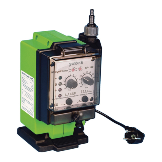
Page 20: Product Components
Product description Product components Designation Function Cover Transparent, to protect the operating panel G 5/8 screw connection for suction and pressure Connection kit D 6-12 pipe Operating panel With display and adjusting elements Lock Screw-on, with holes for lead seal Glass tube fine fuse 5x20, medium time lag Fuse 0.125 A... - Page 21 Product description 3.1.2 Pump head connections Designation Designation Hose connection Suction valve Union nut Dosing membrane Pressure valve Venting membrane Deaeration valve Valve pin Pump head housing Intermediate valve Designation Function Suction pipe From the dosing tank Pressure pipe To the dosing point in the water pipe Recirculation hose Return to the dosing tank 21 | 84...
-
Page 22: Functional Description
(refer to design calculation and chemi- cal resistance list of the GENODOS-Pump GP, order no. 118 949), for instance. The dosing capacity of the pump is designed for 50 Hz. - Page 23 3.2.2 Versions of GENODOS-Pump GP Available variants of the GENODOS pump (refer to chapter 12). GP-6/10 1 digit 6 = dosing capacity 2 digits 10 = control variant GENODOS-Pump GP pumps are available in 3 different control vari- ants: Features GP-../ 10 GP-../ 25 GP-../ 40...
- Page 24 Product description 3.2.3 Displays and settings Designation Function Pulse division or Setting the pulse division and the pulse multiplication pulse multiplication (refer to chapter 7.1.2) factors Setting of different operating modes: 0, T, V and 00, T0, V0 or analogue 0 – 5 V, 1 – 6 V, 0.20 mA, 4 – 20 Operating mode mA with external actuation (refer to chapter 7.1.1).
- Page 25 When set to Ext., the pump only processes signals from external pulse generators. The operation LED indicates that the pump is supplied with mains voltage. With GENODOS-Pump GP-../40 Operating display pumps, each dosing stroke is confirmed by a short flash.
- Page 26 A level probe can be connected to this connection. Input Level switches with pre-warning can also be con- Empty signal nected to GENODOS-Pump GP-../40 pumps. For GENODOS-Pump GP-../40 pumps, only and exclu- sively suction lances and empty signals with pre- warning must be used.
- Page 27 Product description Connection empty signal inlet Designation Designation Connection cable 3-pole (as ac- Level probe (200 µs) cessory 116 093) Level control with advance warning (e.g. float switch) Designation Colour Earth (reference point) BR (brown) Level empty WH (white) Level pre-warning GN (green) ►...
- Page 28 Product description Connection external actuation input Designation Designation Analogue actuation: Hall switch 0 – 5 V, 1 – 6 V, 0 – 20 mA, Transistor actuation NPN 4 – 20 mA Relay contact (normally open Ext. operational release (e.g. contact NO), contacts of water timer, normally closed contact meter e.g.
- Page 29 Product description ► Connect external activators. ► Set the selector switch for automatic actuation (Int. – 10) or external actuation (Ext.). Connection voltage-free alarm signal output Components Components Line socket 3-pole with Pg 7 Connection cable, ÖPVC-OZ screw connection 3x0.5 with wire end ferrules 0.50 mm²...
-
Page 30: Accessories
Product description 3.3 Accessories Your product can be retrofitted with accessories. Please contact your local Grünbeck representative or Grünbeck's headquarters in Hoechstaedt for details. Illustration Product Order no. Connecting cable for fault signal 116 219 (3 m) With line socket 3-pole in grey (order no. -
Page 31: Transport And Storage
Transport and storage Transport and storage 4.1 Transport ► Transport the product in its original packaging only. 4.2 Storage ► Protect the product from the following impacts when storing • Moisture, wetness • Environmental impacts such as wind, rain, snow, etc. •... -
Page 32: Installation
Installation Installation The installation of the system represents a major intervention into the water system and only a qualified specialist may install these systems. Installation example: Installation on dosing tank Designation Designation Dosing tank with automatic agi- Contact water meter tator Pressure maintaining valve Suction lance with suction and... - Page 33 Installation Installation example: Wall mounting Designation Designation Contact water meter Dosing point (dosing group) Digital time control Connection kit Overflow valve Dosing tank with hand mixer Suction lance with suction and Pressure maintaining valve return pipe Dosing line Hand mixer 33 | 84...
-
Page 34: Requirements With Regard To The Installation Site
Installation 5.1 Requirements with regard to the installation site ● The adequately dimensioned installation surface of the sys- tem must be level and provide sufficient strength and load- bearing capacity to support the system's operating weight. ● The installation site must be frost-proof and ensure the sys- tem's protection from direct sunlight, chemicals, dyes, sol- vents and their vapours, etc. -
Page 35: Checking The Scope Of Supply
Shown here as an example of the full scope for GP-../40. Designation Designation Coupling socket 3-pole, black Base plate (empty signal) GENODOS-Pump GP pump Recirculation hose Ø 6/9; PVC with pump head crystal clear, 1500 mm long Connection kit D 6-12, G5/8 Worm drive hose clip NORMA (2x) 8–16/9... -
Page 36: Installing The Dosing Pump
Installation 5.3 Installing the dosing pump Depending on the application of the GENODOS-Pump GP pump, the installation can be carried out individually. The slip-on base plate allows the pump to be mounted horizontally on a bracket/dosing tank or on the floor, or vertically directly on the wall. - Page 37 Installation 5.3.1 Installation types of the base plate Designation Designation Push-to-release mechanism Base plate ► Check the space available on site before installing the pump. ● Space required to remove the pump when mounted horizon- tally (floor mounting) ≥ 240 mm. ●...
- Page 38 Installation 5.3.2 Wall mounting ► Select the fastening material according to the wall situation (recommendation: 4x screws with stainless steel washers). ► The fastening material must be provided by others on site. ► Check that the wall is load-bearing and that the pump can be solidly attached.
- Page 39 Installation 5.3.3 Installation on dosing tank The dosing tank is prepared for mounting the pump with threaded inserts (fastening material included). Designation Designation Fastening screws with washer Base plate 1. Place the base plate on the dosing tank so that the pump can be pushed on from the front.
-
Page 40: Connecting The Lines
Installation 5.4 Connecting the lines The return pipe must be led back to the dosing tank. The hoses must be laid without kinks. Designation Designation Suction pipe from the dosing Pressure pipe to the overflow tank valve and dosing point (acces- sories) Hose clamp NORMA S10/9 Return pipe to dosing tank... -
Page 41: Check For Leaks
Installation 5.5 Check for leaks To prevent the pump from running dry, the pump must be pre-filled with liquid during initial filling. WARNING Discharge of dosing agent if the system is leaking ● Chemical burns caused by the use of alkali, chlorine and acid. - Page 42 Installation 5.5.1 Switch on pump/adjust control unit 1. Establish the power supply – connect the mains plug. 2. Set the internal/external control selector to Int. 10 (for GP- ../40). 3. Set the stroke length controller to 100. » The pump is set to maximum dosing capacity and stroke fre- quency.
- Page 43 Installation 5.5.2 Connect the dosing tank ► Mount all required accessories for the dosing system (refer to accessories for GENODOS-Pump GP pumps). Designation Designation Water withdrawal point for sam- Collecting container (optional) pling and deaeration Dosing point 1. Prepare the dosing agent.
-
Page 44: Start-Up
Start-up Start-up The initial start-up of the product is only allowed to be carried out by the customer service. WARNING Skin and eye contact with dosing solution ● Chemical burns to the eyes, irritation of the skin and respira- tory tract ►... -
Page 45: Establishing Contact Connections
Start-up 6.1 Establishing contact connections The contacts must be pre-assembled (refer to chapter 3.2.4). Designation Designation Screw plug Blind plug Cover Contact sleeve 1. Loosen the screw plug – turn counter-clockwise. 2. Lift up the cover. 3. Unscrew the blind plugs. 4. - Page 46 Start-up 6.1.1 Establish contacts ► Connect the pump to the required contacts – depending on the design of the pump and dosing system (refer to chapter 3.2.4). 1. Establish the contact for empty signal. 2. Establish the contact for alarm signal. When using "external activators", do not connect the contact (4- pole in red) until the functional and leakage check has been carried out (refer to chapter 6.1.2).
- Page 47 Start-up 6.1.2 External actuation 1. Plug the red contact for external actuation into the socket. 2. Set the internal/external control selector to Ext. 6.1.2.1 Actuation by external operational release (timer) Observe the operation manual for the digital time control (order no. 163 950).
- Page 48 Start-up 6.1.3 Set dosing capacity and stroke frequency The dosing capacity (dosing volume H O) is only allowed to be set on the stroke length controller with the pump running (in operation) according to the water pressure. If the GENO-Baktox pump and the chlorine pump for DM-T sys- tems are lead-sealed, the adjustment can be dispensed with.
-
Page 49: Checking Dosing System
Start-up 6.2 Checking dosing system WARNING Discharge of hazardous dosing solution ● Chemical burns on contact of dosing solution with eyes, skin ► Connect the recirculation hose to the dosing tank each time you start up the system. 1. Check that all lines are securely connected. a Retighten the clamps if necessary. -
Page 50: Handing Over The Product To The Owner/Operator
Start-up 4. Completely open a water withdrawal point after the dosing point. 5. Establish a max. dosing capacity. 6. Check the function of the pump. 7. Perform a test run. 8. Fill in the start-up log (refer to chapter 13.1). 6.3 Handing over the product to the owner/oper- ator ►... -
Page 51: Operation/Handling
Operation/handling Operation/handling The schematic overview shows the various operating modes and possible settings of the GP-../40 pump. Schematic overview of the operating modes Mains supply Ext. Int. Divis. T Multiplication V 0-20 mA 4-20 mA 0-5 V 6-109 strk./min 1 : 1 WM pulse : stroke Position 0-9 Position 0-9... - Page 52 Operation/handling ► Set the stroke frequency selector switch to Ext. GENODOS-Pump GP-../40 pumps can store and process a maxi- mum of 65517 incoming pulses with external actuation. With "Mains off" or when switching to another operating mode (operating mode switch), these stored pulses are deleted.
- Page 53 Operation/handling If the function of pulse storage (when the stroke frequency of max. 109 strokes/min. is exceeded) is not desired in the various operating modes (0 / T / V), ► adjust the operating mode switch accordingly to 00, T0 or ●...
-
Page 54: Dosing Capacity
Operation/handling 7.2 Dosing capacity Observe the design calculation (order no. 118 949). In the case of lead-sealed pumps (vp) in the drinking water sector, the preset dosing capacity must not be adjusted. The dosing capacity of the pump is designed for 50 Hz. ►... -
Page 55: Changing Dosing Agent
Operation/handling In case of counter-pressures of > 1 bar (10 mWC) and in case of fluctuating counter-pressures, a pressure maintaining valve must be connected downstream. We recommend to generally use an overflow valve, in particular in case of aggressive media. An overflow valve is a safety device to protect the dosing pump and the corresponding fittings and pipes. - Page 56 Operation/handling WARNING Incorrect use of dosing agent ● Health hazard due to overdosage and/or incorrect dosing agents in drinking water ► Only use dosing agents approved by Grünbeck in the drink- ing water sector. CAUTION Use of the wrong pump version ●...
-
Page 57: Maintenance And Repair
Maintenance and repair Maintenance and repair Maintenance includes cleaning, inspection and servicing of the prod- uct. The responsibility for inspection and maintenance is subject to local and national requirements. The owner/user is responsible for com- pliance with the prescribed maintenance work. By concluding a maintenance contract you ensure that all mainte- nance work will be performed in due time. -
Page 58: Intervals
Maintenance and repair ● These substances will damage plastic components. ► Use a mild/pH-neutral soap solution. ► Use personal protective equipment. ► Only clean the outside of the product. ► Do not use any strong or abrasive cleaning agents. ► Wipe the surfaces with a damp cloth. ►... -
Page 59: Inspection
Maintenance and repair ► As owner/operating company, determine which components have to be inspected and maintained at which intervals (load-dependent). This is subject to the actual conditions, e.g.: Water condition, degree of impurities, environmental in- fluences, consumption, etc. The following interval table shows the minimum intervals for the ac- tivities to be performed. -
Page 60: Maintenance
Maintenance and repair 2. Check whether the dosing system is in operating mode and does not report any faults. 3. Visually inspect the entire dosing system for leakage. 4. Check the dosing solution for contents and shelf life. 8.4 Maintenance Regular work is necessary in order to ensure proper functioning of the product in the long term. - Page 61 Maintenance and repair 8.4.2 Annual maintenance Annual maintenance work requires expert knowledge. This mainte- nance work is only allowed to be performed by the technical ser- vice or by qualified specialists trained by Grünbeck. In addition to the semi-annual maintenance, the following work needs to be done: 5.
-
Page 62: Spare Parts
Maintenance and repair 8.5 Spare parts You can find an overview of the spare parts in the spare parts cata- logue at www.gruenbeck.com. You can obtain the spare parts from the Grünbeck representative responsible for your area. 8.6 Wearing parts Wearing parts are only allowed to be changed out by the technical service. - Page 63 Maintenance and repair 8.6.1 Dismantle pump head ► Rinse the pump with water first. ► Release all pressure from the dosing line before you start to disconnect the pressure connection from the pump head. Designation Designation Valve pin Cross-slot screw Venting duct on the pump head Hexagon socket screws (4 mm) 63 | 84...
- Page 64 Maintenance and repair Pay attention to the following during installation of the pump head: ► When reassembling, first insert the valve pin into the venting duct guide on the pump head to avoid damaging it. 1. Loosen the cross-slotted screw of the cover. 2.
-
Page 65: Fault
Fault Fault WARNING Skin and eye contact with dosing solutions ● Chemical burns to the eyes and irritation of the skin and res- piratory tract ► Use eye protection goggles, protective gloves and sturdy clothing. ► Observe the safety data sheet of the dosing agent. 9.1 Signals Designation Designation... - Page 66 Fault 3. Acknowledge the message/fault by disconnecting and re- connecting the mains plug. Display Explanation Remedy ► Check connection cable LED operation indi- Power failure cator not illuminated and mains voltage ► Check fuses and replace, if Fuses defective necessary ►...
-
Page 67: Observations
Fault 9.2 Observations Observation Explanation Remedy ► Set pump lower Pump does not prime de- Suction head exceeded spite full stroke move- (max. 1.5 m) ment (stroke controller 6 ► Refill dosing agent Liquid below required le- to 100) ► Seal suction connec- Suction connection lea- king tion... - Page 68 Fault Observation Explanation Remedy ► Unplug the mains Dosing monitoring illumi- Motor overload nates plug and plug it in again ► Check counter-pres- sure ► Check mains voltage Mains voltage below 230 V ► Unplug the mains plug and plug it in again ►...
-
Page 69: Shut Down
Shut down 10 Shut down If a relatively long downtime of the system is planned, a pump shut- down must be carried out. 10.1 Temporary shutdown 1. Flush the pump with water if necessary – depending on the active agent. 2. -
Page 70: Dismantling And Disposal
Dismantling and disposal 11 Dismantling and disposal 11.1 Dismantling The work described herein represents an intervention into your wa- ter system. ► Have this work performed by qualified specialists only. 1. Rinse the pump with water. 2. Disconnect the pump from the mains. 3. - Page 71 Dismantling and disposal NOTE Risk to the environment due to incorrect disposal ● Packaging materials are valuable raw materials and can be reused in many cases. ● Incorrect disposal can cause environment pollution. ► Dispose of packaging material in an environmentally sound manner.
-
Page 72: Technical Specifications
Technical specifications 12 Technical specifications Designation Designation Base plate wall mounting Base plate floor mounting 72 | 84... - Page 73 Technical specifications Dimensions and weights GP-../ 10 GP-../ 25 GP-../ 40 A Height with base plate B Total height C Total width D Depth (floor mounting) E Depth (wall mounting) ≥ 240 F Required depth for replacement (floor mounting) ≥ 365 G Required height for replacement (wall mounting) Shipping weight...
- Page 74 Technical specifications Materials GP-../ 10 GP-../ 25 GP-../ 40 Pump head/valves PPO/EPDM (standard), PVDF/Viton (4G), PVDF/FPM/PTFE (GENO-Baktox) Valve balls Borosilicate glass/Hastelloy Seals EPDM (standard), Viton (4G), FKM, GENO-Baktox Membranes EPDM-PTFE-coated Features GP-../ 10 GP-../ 25 GP-../ 40 Adjustable dosing stroke Operating display Indication of empty signal Level pre-warning...
- Page 75 Technical specifications Dosing capacity Order no. PPO/EPDM version (standard) GP-0/.. 0.15 l/h at max. 10 bar 118 110 118 130* 118 150 GP-1/.. 0.9 l/h at max. 10 bar 118 160 118 180* 118 200 GP-2/.. 2.0 l/h at max. 10 bar 118 210 118 230* 118 250...
-
Page 76: Operation Log
Operation log 13 Operation log ► Document the initial start-up and all maintenance activities. ► Copy the maintenance report. GENODOS-Pump GP _________ Serial no.: ___________________ 13.1 Start-up log Customer Name Address Installation/accessories Dosing tanks Type/size Agitator manual automatic Suction lance... - Page 77 Operation log Installation/accessories External actuation Type Connection kit on the pump Type/size/material Dosing Active agent Operating values Operating mode internal external Setting the operating mode Setting the dosing capacity Remarks Start-up Company Service technician Work time certificate (no.) Date/signature 77 | 84...
- Page 78 Operation log Maintenance no.: ___ ► Enter the measured values and operating data. ► Confirm the tests with OK or record any repairs carried out. Work performed ☐ Inspection ☐ Maintenance ☐ Repair Designation Execution confirmed Company: Name: Date: Signature: 78 | 84...
- Page 79 Operation log Maintenance no.: ___ ► Enter the measured values and operating data. ► Confirm the tests with OK or record any repairs carried out. Work performed ☐ Inspection ☐ Maintenance ☐ Repair Designation Execution confirmed Company: Name: Date: Signature: 79 | 84...
- Page 80 EU guidelines in terms of its design, construc- tion and execution. This certificate will become invalid if the system is modified in a way not approved by GENODOS-Pump GP GP-0/..; GP-1/..; GP-2/..; GP-6/..; GP-10/..; GENO-Baktox Serial no.: refer to type plate...
- Page 84 Grünbeck Wasseraufbereitung GmbH Josef-Grünbeck-Str. 1 89420 Hoechstaedt Germany +49 (0)9074 41-0 +49 (0)9074 41-100 For more information go to www.gruenbeck.com info@gruenbeck.com www.gruenbeck.com...
Need help?
Do you have a question about the GENODOS-Pump GP and is the answer not in the manual?
Questions and answers