Table of Contents
Advertisement
Quick Links
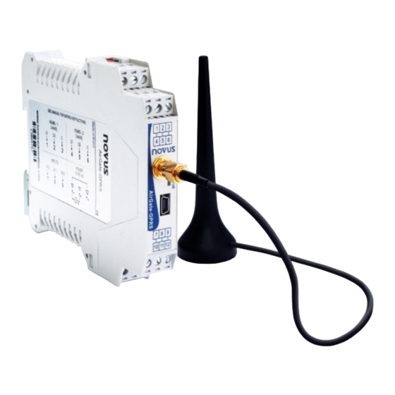
AirGate-GPRS
INSTRUCTION MANUAL
INTRODUCTION ................................................................................................................................................................. 3
TYPICAL APPLICATIONS .................................................................................................................................................. 4
SPECIFICATIONS .............................................................................................................................................................. 7
CONNECTIONS AND INSTALLATION ............................................................................................................................... 8
MECHANICAL INSTALLATION ..................................................................................................................................... 8
DIMENSIONS .......................................................................................................................................................... 8
OPENING THE AIRGATE-GPRS ............................................................................................................................ 8
ELECTRICAL INSTALLATIONS .................................................................................................................................... 9
INSTALLATION RECOMMENDATIONS ................................................................................................................. 9
POWER SOURCE ................................................................................................................................................... 9
RS485 ...................................................................................................................................................................... 9
INPUTS .................................................................................................................................................................. 11
USB INTERFACE .................................................................................................................................................. 12
GPRS INTERFACE ............................................................................................................................................... 12
SIGNAL LIGHT (LED) ....................................................................................................................................................... 13
USB DRIVER INSTALLATION .......................................................................................................................................... 14
WINDOWS 8 ............................................................................................................................................................... 14
DEFINITION AND SELECTION OF SERIAL PORT (COM) - WINDOWS ......................................................................... 19
CONFIGURATION SOFTWARE ....................................................................................................................................... 20
EQUIPMENT SOFTWARE (FIRMWARE) UPDATE .................................................................................................... 20
AIRGATE-GPRS OPERATION ......................................................................................................................................... 21
GPRS INTERFACE ..................................................................................................................................................... 21
AUTHENTICATION AND OTHER DETAILS.......................................................................................................... 21
WITHOUT AUTHENTICATION ........................................................................................................................ 21
OPEN AUTHENTICATION ............................................................................................................................... 21
NAP .................................................................................................................................................................. 21
ANALOG OR DIGITAL INPUT ..................................................................................................................................... 21
RS485 INTERFACES .................................................................................................................................................. 22
RS485 - 1 ............................................................................................................................................................... 23
RS485 - 2 ............................................................................................................................................................... 23
REMOTE CHANNELS ................................................................................................................................................. 23
USB INTERFACE ........................................................................................................................................................ 24
SENDING SMS - ALARMS AND STATUS ................................................................................................................. 24
ALARMS ................................................................................................................................................................ 24
SMS EXAMPLES ................................................................................................................................................... 25
DATA COMMUNICATION AND ROUTING ................................................................................................................. 25
ROUTING .............................................................................................................................................................. 26
ONE RS485 MASTER INTERFACE ................................................................................................................ 26
TWO RS485 MASTER INTERFACES ............................................................................................................. 26
MODBUS COMMANDS AND REGISTERS TABLE .......................................................................................................... 27
SUPPORTED MODBUS COMMANDS ....................................................................................................................... 27
READ HOLDING REGISTERS - 03H ................................................................................................................... 27
WRITE SINGLE REGISTER - 06H ....................................................................................................................... 27
WRITE MULTIPLE REGISTERS - 16H ................................................................................................................. 27
TABLE OF HOLDING REGISTERS ............................................................................................................................ 27
DETAILS ABOUT SOME REGISTERS ....................................................................................................................... 28
REGISTERS 0 AND 1 - SERIAL NUMBER ........................................................................................................... 28
REGISTER 2 - FIRMWARE VERSION ................................................................................................................. 28
REGISTERS 3 AND 4 - VALUE OF THE ANALOG/DIGITAL CHANNEL ............................................................. 28
REGISTERS 5 TO 14 - VALUE OF REMOTE CHANNEL .................................................................................... 28
NOVUS AUTOMATION
V1.0x
1/29
Advertisement
Table of Contents

Related Manuals for Novus AirGate-GPRS

Summary of Contents for Novus AirGate-GPRS
-
Page 1: Table Of Contents
TYPICAL APPLICATIONS ..............................4 SPECIFICATIONS ................................7 CONNECTIONS AND INSTALLATION ..........................8 MECHANICAL INSTALLATION ............................. 8 DIMENSIONS ................................8 OPENING THE AIRGATE-GPRS ..........................8 ELECTRICAL INSTALLATIONS ............................ 9 INSTALLATION RECOMMENDATIONS ......................... 9 POWER SOURCE ..............................9 RS485 ..................................9 INPUTS .................................. 11 USB INTERFACE .............................. - Page 2 AirGate-GPRS REGISTERS 31 TO 45 – SIM CARD IDENTIFICATION ..................28 REGISTER 46 – GSM SIGNAL LEVEL ......................... 28 REGISTER 51 – STATUS 1........................... 28 REGISTER 52 – STATUS 2........................... 28 WARRANTY ..................................29 NOVUS AUTOMATION 2/29...
-
Page 3: Introduction
AirGate-GPRS INTRODUCTION Ideal for machine to machine (M2M) telemetric applications, the AirGate-GPRS allows for the supervision of a network with Modbus serial communication for more than one master. One of the masters can be remote, communicating using a TCP/IP connection on GPRS using the cloud. Another master can be locally connected supervisory software. The second RS485 interface can be configured as a Modbus slave, allowing a third master, such as a local IHM, to access the slaves, or as a Modbus master, allowing a new branch of the network with more slaves communicating. -
Page 4: Typical Applications
Below are examples of some AirGate-GPRS applications: 1. Remote monitoring without local monitoring With this application, the AirGate-GPRS allows remote access to the data of the Modbus RTU network using the cellular network (GSM/GPRS) and the sending of alarm and status messages (SMS). - Page 5 2. Remote monitoring with local monitoring In this application, AirGate-GPRS is inserted in a Modbus network that needs local supervision (often it is an existing Modbus network). Besides performing the role of a USB-RS485 converter, it allows remote access to data from the Modbus RTU network using the cellular network (GSM/GPRS) and the sending of alarm and status messages (SMS).
- Page 6 4. Remote monitoring using only SMS In this application, the AirGate-GPRS can either be or not be inserted in a Modbus network. The monitoring of the desired variables is made only by text messages that state the periodic status of a few variables and alarm type conditions.
-
Page 7: Specifications
Wire section used: AWG 28 a 12. Recommended torque: 4 kgf·cm. Analog Entries: The types of entry signals accepted by AirGate-GPRS and their minimum measurement bands are selected in the Configuration software and are listed in the following table. TYPE OF INPUT... -
Page 8: Connections And Installation
Fig. 01 – Dimensions of the AirGate-GPRS OPENING THE AIRGATE-GPRS In order to open the AirGate-GPRS, you must press the orange lockers located on both sides of the enclosure and pull the frontal cover very carefully, just like shown in Fig. 02. -
Page 9: Electrical Installations
(RS485-1), while terminals 4, 5, and 6 belong to the second interface RS485/Modbus (RS485-2). Terminals 7, 8, and 9 are for the inputs (analog or digital) of the equipment. Terminals 10, 11, and 12 are used to feed the AirGate-GPRS. - Page 10 AirGate-GPRS • Master • Slave NOVUS AUTOMATION 10/29...
-
Page 11: Inputs
There are two input channels that can be individually configured using internal jumpers such as input 4-20 mA, input 0-10 V or digital input. There is no insulation between channels. The jumper access requires the opening of the AirGate-GPRS. Their location can be seen in the following illustration: The AirGate-GPRS is factory configured as a digital input in both channels. -
Page 12: Usb Interface
Channels connection in the terminals should be done as shown in the figure on the left. Check the correct connection polarity. USB INTERFACE The AirGate-GPRS has a USB interface that can be connected to a computer for configuring or monitoring. The USB cable is supplied along with the equipment. GPRS INTERFACE This interface requires a compatible antenna, supplied with the equipment, to be connected at the external SMA plug. -
Page 13: Signal Light (Led)
• The led will flash rapidly when it connects to the GSM network; • The led will flash twice rapidly when the connection with the remote server is established. After powered, AirGate-GPRS led can take a few seconds to start flashing! NOVUS AUTOMATION... -
Page 14: Usb Driver Installation
Following are the steps and guidance screens for the driver installation. WINDOWS 8 1. Connect the AirGate-GPRS in a USB port on your computer. Windows will try to install a driver automatically and will not succeed, because the necessary driver is not in its standard library. - Page 15 AirGate-GPRS 3. Locate the AirGate-GPRS (probably with an icon with an exclamation mark next to it) and double-click on it. 4. Click on the button "Update Driver...". NOVUS AUTOMATION 15/29...
- Page 16 AirGate-GPRS 5. Ask to "Browse my computer for driver software". 6. Enter the path of the folder where the drivers are located (the product CD or folder where you saved them when downloaded from the site.) NOVUS AUTOMATION 16/29...
- Page 17 AirGate-GPRS 7. Wait for the installation to take start. 8. Windows will indicate that it cannot verify the editor of this driver. Confirm to install anyway! NOVUS AUTOMATION 17/29...
- Page 18 AirGate-GPRS 9. A message indicating successful installation will display. 10. Returning to the Device Manager screen, you can check which virtual serial port is allocated to the AirGate-GPRS. NOVUS AUTOMATION 18/29...
-
Page 19: Definition And Selection Of Serial Port (Com) - Windows
AirGate-GPRS DEFINITION AND SELECTION OF SERIAL PORT (COM) - WINDOWS The serial port associated with AirGate-GPS is automatically defined by the operating system a few moments after connecting the AirGate-GPS. The user can easily identify or change the COM port associated with AirGate-GPS: Control Panel / System / Hardware / Device Manager / COM &... -
Page 20: Configuration Software
After applying the communication configuration, the system is ready to read the the AirGate-GPRS configuration by clicking on the Search button located in the lower left corner of the main window. In order to make the search faster, configure the Modbus address range to search correctly (do NOT use “Temporary”... -
Page 21: Airgate-Gprs Operation
As soon as AirGate-GPRS is turned on, as long as there is a SIM Card in the internal connector and the equipment is configured properly, it attempts to connect to a remote (machine-to-machine) server to make their registers and remote consultations available. -
Page 22: Rs485 Interfaces
(highest and lowest values considering the work range of the AirGate-GPRS for the type of entry chosen, or for digital input chosen, or for digital inputs, values associated with logic states “0”... -
Page 23: Rs485 - 1
RS485 - 1 The RS485 interface of the AirGate-GPRS is located in terminals 1, 2, and 3 and behaves as a Modbus RTU master, allowing data from other devices on the bus to be read by AirGate-GPRS either directly (remote channels) or by other masters using the AirGate-GPRS (gateway). -
Page 24: Usb Interface
If there is more than one alarm, the AirGate-GPRS will send all the active alarms to the configured destinations in the order of the 1st to the last, and the user can notice a small delay in the receipt of the messages between the configured numbers. -
Page 25: Sms Examples
“Alarm” message “Channel Error” message DATA COMMUNICATION AND ROUTING The AirGate-GPRS has several communication interfaces. Among them, we can highlight some that can be used as Modbus slaves: • RS485, acting as a slave in the Modbus RTU protocol. NOVUS AUTOMATION... -
Page 26: Routing
If we use only the RS485 – 1 interface configured and a Modbus master, all of the commands coming from different slave interfaces (USB, GPRS, and/or RS485 - 2) that are not destined for the AirGate-GPRS will be routed to this interface. -
Page 27: Modbus Commands And Registers Table
MODBUS COMMANDS AND REGISTERS TABLE The AirGate-GPRS accepts some Modbus commands that are sent to its Modbus’ own address, operating as a network slave. Commands forwarded to other slaves (routing) will be sent in a transparent way. The following listed Modbus RTU commands (functions) are implemented, and these are interpreted by AirGate-GPRS. -
Page 28: Details About Some Registers
10, depending on the number of configured decimal points. Example: Value of 31.78 will be read as 3178. REGISTERS 31 TO 45 – SIM CARD IDENTIFICATION Code IMSI inscribed on the SIM card connected to the AirGate-GPRS (in ASCII). REGISTER 46 – GSM SIGNAL LEVEL Indicates the current level of GSM signal intensity in dBm. - Page 29 AirGate-GPRS WARRANTY Warranty conditions are available on our web site: www.novusautomation.com. NOVUS AUTOMATION 29/29...
Need help?
Do you have a question about the AirGate-GPRS and is the answer not in the manual?
Questions and answers