Table of Contents
Advertisement
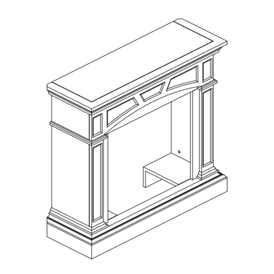
ITEM #0328248
WOOD FIREPLACE MANTEL
Cedar Ridge
MODEL #CRHFD400RT-M-M
®
h e a r t h
Español p. 17
Questions, problems, missing parts? Before returning to your retailer, call our
customer service department at 1-866-573-0674, 8:00 a.m - 4:30 p.m., EST,
Monday - Friday or e-mail customerservice@usaprocom.com.
LS-FBD400-M3-1101
Advertisement
Table of Contents

Related Manuals for Cedar Ridge CRHFD400RT-M-M


Summary of Contents for Cedar Ridge CRHFD400RT-M-M
- Page 1 ITEM #0328248 WOOD FIREPLACE MANTEL Cedar Ridge MODEL #CRHFD400RT-M-M ® h e a r t h Español p. 17 Questions, problems, missing parts? Before returning to your retailer, call our customer service department at 1-866-573-0674, 8:00 a.m - 4:30 p.m., EST, Monday - Friday or e-mail customerservice@usaprocom.com.
-
Page 2: Product Specifications
PRODUCT SPECIFICATIONS... -
Page 3: Package Contents
PACKAGE CONTENTS PART DESCRIPTION Quantity Panel Left Upper Panel Right Upper Panel Left Lower Panel Right Lower Panel Base Top Triangle Panel Backboard Set Square Support... -
Page 4: Hardware Contents
HARDWARE CONTENTS Picture Picture Part Description Quantity (Shown to size) Part Description Quantity (Shown to size) ST4 Screw Cam Dowel 5/8 in. Mounting Cam Lock Bracket (not actual size) Wall Anchor White Key ST4 Screw ST4 Screw 1 3/ 1 6 in. 1 9/ 1 6 in. - Page 5 ASSEMBLY INSTRUCTIONS Fig.1 1. Fasten the Left Upper Panel (C) and the Left Lower Panel (E) with M6 Screw 1-3/8 in. (JJ) as shown in Fig 1. Do the same thing for the Right Upper Panel (D) and the Right Lower Panel (F).
- Page 6 Fig. 3 3. Insert Cam Locks (BB) into the Left Lower Panel (E) and the Right Lower Panel (F), screw in Cam Dowels (AA) into Base (G). Attach Base (G) into assembled frame (B, C, D, E, F) by tightening the Cam Locks (BB) as shown in Fig 3.
- Page 7 Fig. 5 5. Insert Cam Locks (BB) into Panel (B), the Left Upper Panel (C) and the Right Upper Panel (D), screw in Cam Dowels (AA) into Top (A). Attach Top (A) into assembled frame (B, C, D, E, F) by tightening the Cam Locks (BB) as shown in Fig 5.
- Page 8 Fig. 7 7. After assembling the mantel, lift upright and push the insert from the front of the mantel as shown in Fig 7. Fig. 8 8. Position the fireplace to the desired place as shown in Fig 8.
- Page 9 ASSEMBLY INSTRUCTIONS CONTINUED (CORNER MANTEL) Fig.9 9. Turn the Top (A) Panel over. Using the Con- nector Brackets (GG) that supplied, connect the Top (A) to the Top Triangle Panel (H) with ST4 Screw 5/8 in. (FF) as shown in Fig 9. Hardware Used x 18 ST4 Screw - 5/8 in.
- Page 10 Fig. 11 11. Fasten the batten with ST4Screw 1-9/16 in. (II) to the Top (A) as shown in Fig 11. Hardware Used ST4 Screw - 1 9/ 1 6 in. Fig. 12 12. Attach the left and right Backboard (I) trim pieces to the back of the fireplace with ST4 Screw 1-3/16 in.
- Page 11 Fig. 13 13. After assembling the mantel, lift upright and push the insert from the front of the mantel as shown in Fig 13. Fig. 14 14. Drill two holes (5/16 in.) in the corner Mitered Corner where the fireplace is to be displayed. Drill Joints the first hole 39 5/16 in.
- Page 12 Fig. 15 15. Attach the triangular wood block to the holes Mitered Corner drilled in step 8 with ST4 Screw - 2 3/8 in. (EE) as Joints shown in Fig. 15. This block is used to support the Set Square Support (J). For thin walls, insert white key (HH) into wall anchor and push to “pop”...
-
Page 13: Replacement Parts
REPLACEMENT PARTS NOTE: Use only original replacement parts. This will protect your warranty coverage for parts replaced under warranty. PARTS UNDER WARRANTY Call Customer Service toll free at (1-866-573-0674) for referral information. When calling Customer Service, have ready: • Your name •... -
Page 14: Replacement Parts List
REPLACEMENT PARTS LIST For replacement parts, call our customer service department at 1-866-573-0674, 8:00 a.m - 4:30 p.m., EST, Monday - Friday or e-mail customerservice@usaprocom.com. Part. Description Part # Cam Dowel PCAM-023 Cam Lock PCAM-023 Wall Anchor ML066 - 01 ST4 Screw 1 3/16 in. -
Page 15: Year Limited Warranty
2-YEAR LIMITED WARRANTY The manufacturer warrants this product to be free from defects in workmanship and material present at time of shipment from the factory for two (2) years from the date of purchase. This warranty applies only to the original purchaser. The manufacturer agrees to correct such defect at no charge or, at our option, replace the product with a comparable or superior model.
Need help?
Do you have a question about the CRHFD400RT-M-M and is the answer not in the manual?
Questions and answers