Table of Contents
Advertisement
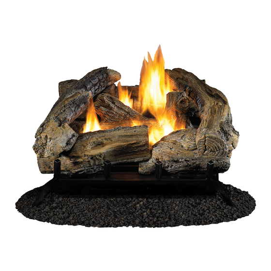
Cedar Ridge
h e a r t h
WARNING: If the information in this manual is not
followed exactly, a fire or explosion may result causing
property damage, personal injury or loss of life.
— Do not store or use gasoline or other flammable va-
pors and liquids in the vicinity of this or any other
appliance.
— WHAT TO DO IF YOU SMELL GAS
• Do not try to light any appliance.
• Do not touch any electrical switch; do not use any
phone in your building.
• Immediately call your gas supplier from a neighbor's
phone. Follow the gas supplier's instructions.
• If you cannot reach your gas supplier, call the fire
department.
— Installation and service must be performed by a quali-
fied installer, service agency or the gas supplier.
WARNING: This appliance is equipped for Natural and
Propane gas. Field conversion is not permitted other than
between natural or propane gases.
Questions, problems, missing parts? Before returning to your retailer, call
our customer service department at 1-866-573-0674, 8:00 am - 4:30 pm CST,
Monday through Friday or email customerservice@usaprocom.com
VENT-FREE GAS LOGS
OWNER'S OPERATION AND
INSTALLATION MANUAL
®
CRHLD18TB AND CRHLD24TB
MODELS
PFS
®
US
Advertisement
Table of Contents

Related Manuals for Cedar Ridge CRHLD18TB


Summary of Contents for Cedar Ridge CRHLD18TB
- Page 1 INSTALLATION MANUAL ® h e a r t h MODELS CRHLD18TB AND CRHLD24TB ® WARNING: If the information in this manual is not followed exactly, a fire or explosion may result causing property damage, personal injury or loss of life.
-
Page 2: Table Of Contents
TABLE OF CONTENTS Safety ............3 Operation ..........20 Qualified Installing Agency ......4 Inspecting Burners........22 Specifications ..........5 Care And Maintenance ......23 Product Features ........5 Troubleshooting ........25 Product Identification ......... 5 Parts ............28 Local Codes..........6 Replacement Parts ........ -
Page 3: Safety
SAFETY IMPORTANT: Read this owner’s WARNING: Any change to this heater or its controls can manual carefully and completely before trying to assemble, op- be dangerous. erate, or service this heater. WARNING: Do not allow fans Improper use of this heater can to blow directly into fireplace. -
Page 4: Qualified Installing Agency
SAFETY 1. Do not place Propane/LP supply tank(s) 10. Operating heater above elevations of inside any structure. Propane/LP supply 4,500 feet could cause pilot outage. tank(s) must be placed outdoors. 11. To prevent performance problems, do 2. This heater shall not be installed in a not use propane/LP fuel tank of less than bedroom or bathroom. -
Page 5: Specifications
SPECIFICATIONS Model CRHLD18TB Model CRHLD24TB Ignition Electronic Piezo Ignitor Gas Type Natural Gas Propane Gas Natural Gas Propane Gas Input Rating 30,000 Btu/Hr 30,000 Btu/Hr 32,000 Btu/Hr 32,000 Btu/Hr Manifold Pressure 4" W.C. 9" W.C. 4" W.C. 9" W.C. Inlet Gas Pressure* (inches Max. -
Page 6: Local Codes
LOCAL CODES Install and use heater with care. Follow all State of Massachusetts: The installation local codes. In the absence of local codes, must be made by a licensed plumber or use the latest edition of The National Fuel gas fitter in the Commonwealth of Mas- Gas Code, ANSI Z223.1/NFPA 54*. -
Page 7: Air For Combustion And Ventilation
AIR FOR COMBUSTION AND VENTILATION heat loss in homes. Home owners weather WARNING: This heater shall strip and caulk around windows and doors not be installed in a confined space to keep the cold air out and the warm air in. or unusually tight construction During heating months, home owners want their homes as airtight as possible. - Page 8 AIR FOR COMBUSTION AND VENTILATION DETERMINING FRESH-AIR FLOW FOR HEATER LOCATION Determining if You Have a Confined or Unconfined Space Use this work sheet to determine if you have 4. Compare the maximum Btu/Hr the space a confined or unconfined space. can support with the actual amount of Btu/ Hr used.
- Page 9 AIR FOR COMBUSTION AND VENTILATION VENTILATION AIR Ventilation Air From Inside Building This fresh air would come from an adjoining 1 and 2, Figure 2). You can also remove door unconfined space. When ventilating to an into adjoining room (see option 3, Figure 2). adjoining unconfined space, you must provide Follow the National Fuel Gas Code, ANSI two permanent openings: one within 12"...
-
Page 10: Installation
INSTALLATION NOTICE: This heater is intended WARNING: Never install the for use as supplemental heat. heater Use this heater along with your • in a bedroom or bathroom primary heating system. Do not • in a recreational vehicle install this heater as your pri- •... - Page 11 INSTALLATION IMPORTANT: Vent-free heaters add moisture to the air. Although this is beneficial, installing heater in rooms without enough ventilation air may cause mildew to form too much moisture. See Air for Combustion and Ventilation, pages 7 through 9. Before beginning assembly or operation of the product, make sure all parts are present.
- Page 12 INSTALLATION If Using Mantel at least 8" up. If noncombustible material is less than 12", you must install the fireplace You must have noncombustible material(s) hood accessory. Even if noncombustible above the fireplace opening. Noncombustible material is more than 12", you may need the materials (such as slate, marble, tile, etc.) hood accessory to deflect heat away from must be at least 1/2"...
- Page 13 INSTALLATION FLOOR CLEARANCES A. If installing appliance on the floor level, B. If combustible materials are less than 14" you must maintain the minimum distance to the fireplace, you must install appliance of 14" to combustibles (see Figure 8). at least 5" above the combustible flooring (see Figure 9).
- Page 14 INSTALLATION For changing from natural gas 4. Remove hex plug (with wrench provided) supply to propane supply: from propane/LP gas inlet of regulator (see Figure 11). Install hex plug into NG 1. Remove bottom screw from cover plate. inlet of regulator. Install gas line into LP Rotate to expose fuel selection device inlet of regulator.
- Page 15 INSTALLATION CONNECTING TO GAS SUPPLY WARNING: A qualified ser- CAUTION: For natural gas, vice technician must connect check your gas line pressure heater to gas supply. Follow all before connecting heater to gas local codes. line. Gas line pressure must be no greater than 10.5"...
- Page 16 INSTALLATION Typical Inlet Pipe Diameters Install sediment trap in supply line as shown Use 3/8" black iron pipe or greater. Installa- in Figure 14. Place sediment trap where it is tion must include an equipment shutoff valve, within reach for cleaning. Place sediment trap union, and plugged 1/8"...
- Page 17 INSTALLATION CHECKING GAS CONNECTIONS WARNING: Never use an open WARNING: Test all gas piping flame to check for a leak. Apply and connections, internal and a noncorrosive leak detection external to unit, for leaks after fluid to all joints. If bubbles form, installing or servicing.
- Page 18 Flames contact- ing logs will create soot. Grate Figure 19 - Heater Base Assembly Model CRHLD18TB (18" Log Set) 1. Insert pins on the back of log #1 into slots Log #1 in rear log bracket on heater base, and Log #2 tighten nuts (see Figure 20).
- Page 19 INSTALLATION 4. Insert pins on the back of log #4 into slots 6. Insert the recessed hole on the bottom of in front log bracket on heater base, and log #6 onto pin on log #1, with the other tighten nuts (see Figure 21). end placed on log #3 (see Figure 22).
-
Page 20: Operation
INSTALLATION Battery Instructions • Be sure to observe proper polarity (+/-) CAUTION: Do not mix old and when installing or replacing the batteries. new batteries. Do not mix alka- Damage due to improper battery installation may void the warranty on the product. line, standard (carbon - zinc), or rechargeable (nickel - cadmium) •... - Page 21 OPERATION 1. STOP! Read the safety information on 7. Keep control knob pressed in for 30 sec- page 20. onds after lighting pilot. After 30 seconds, release control knob. 2. Make sure equipment shutoff valve is fully Note: If pilot goes out, repeat steps 7 open.
-
Page 22: Inspecting Burners
OPERATION THERMOSTATIC CONTROL OPERATION The thermostatic control used on this model room temperature drops below the set tem- differs from standard thermostats. Standard perature. The control knob can be set to any thermostats simply turn the burner on and off. comfort level between HIGH (5) and LOW (1). -
Page 23: Care And Maintenance
Approx. 3"-6" Above Top of Logs INSPECTING BURNERS BURNER FLAME PATTERN Figure 30 shows a correct burner flame pattern. Figure 31 shows an incorrect burner flame pattern. If burner flame pattern is incorrect then: • turn heater off (see To Turn Off Gas to Appliance, page 21). •... - Page 24 CARE AND MAINTENANCE BURNER INJECTOR HOLDER AND PILOT AIR INLET HOLE We recommend that you clean the unit ev- 4. Check the injector holder located at the ery 2,500 hours of operation or every three end of the burner tube again. Remove any months.
-
Page 25: Troubleshooting
TROUBLESHOOTING WARNING: If you smell gas: • Shut off gas supply. • Do not try to light any appliance. • Do not touch any electrical switch; do not use any phone in your building. • Immediately call your gas supplier from a neighbor’s phone. Fol- low the gas supplier’s instructions. - Page 26 TROUBLESHOOTING Problem Possible Cause Corrective Action ODS/pilot lights but flame 1. Control knob is not fully 1. Press in control knob fully. goes out when control pressed in. knob is released. 2. Control knob is not pressed 2. After ODS/pilot lights, keep in long enough.
- Page 27 TROUBLESHOOTING Problem Possible Cause Corrective Action Slight smoke or odor 1. Residues from manufactur- 1. Problem will stop after a few during initial operation. ing process. hours of operation. Heater produces a whis- 1. Turning control knob to high 1. Turn control knob to low tling noise when burner position when burner is cold.
-
Page 28: Parts
PARTS MODELS CRHLD18TB CRHLD24TB CRHLD24TB 12-1 12-1 CRHLD18TB 12-3 12-2 12-2 12-3 12-4 12-4 12-5 12-7 12-9 12-6 12-5 12-8 www.usaprocom.com 200028-01A... - Page 29 PARTS MODELS CRHLD18TB CRHLD24TB This list contains replaceable parts for your heater. When ordering replacement parts, follow the instructions listed under Replacement Parts on page 30 of this manual. ITEM CRHLD18TB CRHLD24TB DESCRIPTION WYL006-01D WYL006-02D Mid Log Bracket WYL005-01F WYL005-01F...
-
Page 30: Replacement Parts
REPLACEMENT PARTS Note: Use only original replacement parts. This will protect your warranty coverage for parts replaced under warranty. PARTS UNDER WARRANTY Contact authorized dealers of this product. • Model and serial number of your heater If they can’t supply original replacement •... -
Page 31: Service Hints
SERVICE HINTS When Gas Pressure Is Too Low • pilot will not stay lit • burners will have delayed ignition • fireplace will not produce specified heat • propane/LP gas supply might be low (propane/LP units only) You may feel your gas pressure is too low. If so, contact your local gas supplier. TECHNICAL SERVICE You may have further questions about installation, operation, or troubleshooting. -
Page 32: Warranty
WARRANTY KEEP THIS WARRANTY Model _______________________________ Serial No. ____________________________ Date Purchased _______________________ Keep receipt for warranty verification. REGISTER YOUR PRODUCT AT WWW.USAPROCOM.COM IMPORTANT: We urge you to register your product within 10 days of date of installation, complete with entire serial number which can be found on the rating plate. Please fill out the warranty infor- mation above for your personal records.
Need help?
Do you have a question about the CRHLD18TB and is the answer not in the manual?
Questions and answers