Advertisement
Quick Links
A l l t e s t I n s t r u me n t s , I n c .
5 0 0 C e n t r a l A v e .
F a r mi n g d a l e , N J 0 7 7 2 7
P : ( 7 3 2 ) 9 1 9 - 3 3 3 9
F : ( 7 3 2 ) 9 1 9 - 3 3 3 2
a l l t e s t . n e t
s s a l e s @ a l l t e s t . n e t
T h e t e s t & me a s u r e me n t
e q u i p me n t y o u n e e d a t
t h e p r i c e y o u w a n t .
A l l t e s t c a r r i e s t h e w o r l d ' s l a r g e s t s e l e c t i o n o f
u s e d / r e f u r b i s h e d b e n c h t o p t e s t & me a s u r e me n t
e q u i p me n t a t 5 0 % t h e p r i c e o f n e w .
O O u r e q u i p me n t i s g u a r a n t e e d w o r k i n g , w a r r a n t i e d , a n d
a v a i l a b l e w i t h c e r t i f i e d c a l i b r a t i o n f r o m o u r i n - h o u s e s t a f f
o f t e c h n i c i a n s a n d e n g i n e e r s .
• 1 0 + f u l l t i me t e c h n i c i a n s w i t h o v e r 1 5 0 y e a r s o f
s p e c i a l i z a t i o n
• 9 0 d a y w a r r a n t y & 5 d a y r i g h t o f r e t u r n o n a l l
e q u i p me n t
• • 1 - 3 y e a r w a r r a n t i e s f o r n e w a n d
p r e mi u m- r e f u r b i s h e d e q u i p me n t
• E v e r y u n i t t e s t e d t o O E M s p e c i f i c a t i o n s
• S a t i s f a c t i o n g u a r a n t e e d
Y o u h a v e p l a n s , w e w i l l h e l p y o u a c h i e v e t h e m.
A n y p r o j e c t . A n y b u d g e t .
t
G e t a q u o t e t o d a y !
C C a l l ( 7 3 2 ) 9 1 9 - 3 3 3 9 o r e ma i l s a l e s @a l l t e s t . n e t .
Advertisement

Subscribe to Our Youtube Channel
Related Manuals for Keithley 182-M


Summary of Contents for Keithley 182-M
- Page 1 T h e t e s t & me a s u r e me n t e q u i p me n t y o u n e e d a t t h e p r i c e y o u w a n t . A l l t e s t I n s t r u me n t s , I n c .
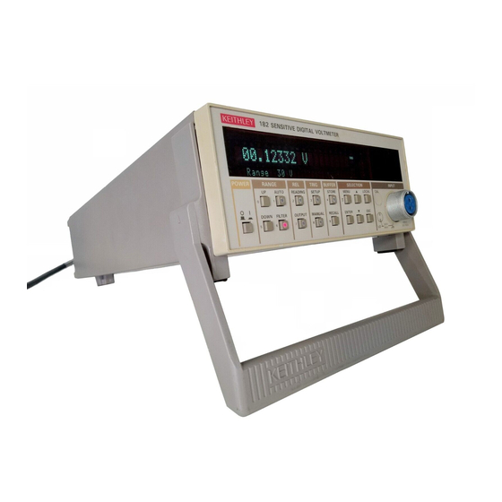
- Page 2 Model 182 Sensitive Digital Voltmeter Quick Reference Guide A G R E A T E R M E A S U R E O F C O N F I D E N C E...
- Page 3 IEEE-488 operation for the Model 182 Sensitive Digital Voltmeter. For detailed Model 182 information, consult the Model 182 Instruction Manual. © 1990, Keithley Instruments, Inc. All Rights Reserved Cleveland, Ohio, U.S.A. Document Number: 182-903-01 Rev. B...
-
Page 4: Table Of Contents
TABLE OF CONTENTS SAFETY PRECAUTIONS ........3 CONTROL SUMMARY ........... 8 TEST CONNECTIONS ......... 14 DEVICE DEPENDENT COMMANDS ....15 DATA FORMATS ........... 23 SRQ MASK AND SERIAL POLL BYTE ....25 ALTERNATE OUTPUT WORD FORMATS ... 26... -
Page 5: Safety Precautions
SAFETY PRECAUTIONS The following safety precautions should be observed before using this product and any associated instru- mentation. Although some instruments and accesso- ries would normally be used with non-hazardous volt- ages, there are situations where hazardous conditions may be present. This product is intended for use by qualified person- nel who recognize shock hazards and are familiar with the safety precautions required to avoid possible in-... - Page 6 Only properly trained service personnel may perform installation and service procedures. Keithley products are designed for use with electrical signals that are rated Installation Category I and In- stallation Category II, as described in the International Electrotechnical Commission (IEC) Standard IEC 60664.
- Page 7 Do not connect switching cards directly to unlimited power circuits. They are intended to be used with im- pedance limited sources. NEVER connect switching cards directly to AC mains. When connecting sources to switching cards, install protective devices to limit fault current and voltage to the card.
- Page 8 Do not exceed the maximum signal levels of the in- struments and accessories, as defined in the specifi- cations and operating information, and as shown on the instrument or test fixture panels, or switching card. When fuses are used in a product, replace with same type and rating for continued protection against fire hazard.
- Page 9 Keithley Instruments to maintain accuracy and functionality of the product.) If you are unsure about the applicability of a replace- ment component, call a Keithley Instruments office for information. To clean an instrument, use a damp cloth or mild, water based cleaner.
-
Page 10: Control Summary
CONTROL SUMMARY RANGE Use UP and DOWN to manually select desired mea- surement range; 3mV, 30mV, 300mV, 3V, or 30V. Present range is displayed on status line. Press AUTO to turn auto-range on or off. Unit upranges at overflow point (±3,029,999 counts) and downranges at 9.33% of full range when AUTO is enabled. - Page 11 to scroll through selections, ENTER to select, or ESC to cancel selection. TRIGGER MODE: select multiple (continu- ous with one trigger) or one-shot (one read- ing per trigger). TRIGGER SOURCE: select external, manual, disabled, or IEEE-488 X, GET or talk triggers. TRIGGER DELAY: program desired trig- ger delay (time between trigger and read- ing in one-shot trigger mode): 0sec-...
- Page 12 SELECTION to scroll through MENU, SETUP, and RE- CALL selections. Press ENTER to choose displayed selection and move down one menu level (where ap- plicable). Press ESC to cancel displayed selection and move up one menu level (where applicable). Use MENU to access operating modes summarized below.
- Page 13 Press LOCAL to cancel remote (REM on) when the instrument is used over the IEEE-488 bus. LOCAL will be locked out when the bus LLO command is in effect. FACTORY DEFAULT CONDITIONS Description Default State Range 30V, auto-range off Reading relative Off, value =0V Analog Filter Digital Filter...
- Page 14 ERROR MESSAGES...
-
Page 16: Test Connections
TEST CONNECTIONS Note: Use only clean copper-to-copper connections to minimize thermals Low thermal cable (Model 1506 or Equivalent) KEITHLEY 182 SENSITIVE DIGITAL VOLTMETER 182.3165 mV TALK Range 300mV LSTN POWER RANGE TRIG BUFFER SELECTION INPUT AUTO READING SETUP STORE MENU... -
Page 17: Device Dependent Commands
DEVICE DEPENDENT COMMANDS NOTE: Corresponding lower-case command letters may be used in place of upper-case command letters. Display ASCII String Restore display to normal A1, string Display string A2, string Display string and store in EEROM Display string stored in EEROM NOTE: String must be surrounded by single quotes. - Page 18 Measure and Analog Output Source Calibration C0, value Calibrate measure positive full scale C1, value Calibrate measure negative full scale Calibrate measure zero offset C3, value Calibrate divider full scale Calibrate divider zero Select positive full scale output C6, value Calibrate positive full scale output Select zero output value C8, value...
- Page 19 Reading Format Reading only Reading with prefix Reading with buffer location Reading with buffer location and prefix Reading with time stamp Reading with time stamp and prefix Reading with time stamp and location Reading with time stamp, location, and prefix Immediate Trigger and Self-test Initiate manual trigger Perform memory test...
- Page 20 EOI, Bus Hold-off on X Enable EOI, enable bus hold-off on X Disable EOI, enable bus hold-off on X Enable EOI, disable bus hold-off on X Disable EOI, disable bus hold-off on X Save and Recall Setup Save current setup as power-on Recall factory default setup Recall power-on setup SRQ Mask...
- Page 21 Analog Filter Configuration Configure analog filter off Configure analog filter on Digital Filter Configuration Configure digital filter off Configure fast response Configure medium response Configure slow response Trigger Interval Qvalue Interval=value in msec (10-999 999msec) Range Enable auto-range 3mV range 30mV range 300mV range 3V range...
- Page 22 Integration Period Line cycle integration period 3msec integration period 100msec integration period Trigger Mode and Source Multiple on talk One-shot on talk Multiple on GET One-shot on GET Multiple on X One-shot on X Multiple on external One-shot on external Multiple on manual (MANUAL key or H0X) One-shot on manual (MANUAL key or H0X) Disable all triggers...
- Page 23 Alternate Output Send machine status Send error conditions Send firmware revision Send buffer length Send buffer average Send buffer standard deviation Send reading relative value Send analog output relative value Send analog output gain value Send trigger interval Send trigger delay Send calibration constants Send calibration lock status Send Model 181-like machine status...
- Page 24 Execute Execute other device-dependent commands Terminators <CR LF> <LF CR> <CR> <LF> <CR LF> <LF CR> Reading Relative Disable reading relative Enable reading relative using next reading Z2, value Enable reading relative using value Enable reading relative, use present value...
-
Page 25: Data Formats
DATA FORMATS Buffer Prefix Location Time (G1, G3, G5, G7) (G2, G3, G6, G7) Stamp Mantissa Exponent (G4, G5, G6, G7) NDCV+1.820000E+00, 0000, 000000.000<term+EOI> Field Separators DCV = Normal Reading MAX = Maximum buffer reading (F3) MIN = Minimum buffer reading (F4) N = Normal O = Overflow Notes : 1. - Page 26 Buffer Time Prefix Mantissa Exponent Location Stamp NMAX+1.820000E+00, 0001, 000000.00<term+EOI> Notes : 1. G7 reading format shown. Presence of prefix, buffer location, and time stamp depends on selected data format. 2. Buffer location and time stamp values are at location of maximum buffer reading. Figure 3.
-
Page 27: Srq Mask And Serial Poll Byte
SRQ MASK AND SERIAL POLL BYTE Decimal Weighting Bit Position 1 = Ready for Trigger 1 = Reading Done 1 = RQS 1 = Buffer Half Full 1 = Error 1 = Buffer Full 1 = Ready for Command 1 = Reading Overflow Note : Bit 6 (RQS) not used in SRQ mask Figure 5. -
Page 28: Alternate Output Word Formats
ALTERNATE OUTPUT WORD FORMATS Model Note: Default values shown Number 182B1F0G1I0J0K0M000N1O0P2R5S0T06V0Y0Z0<term + EOI> B (Resolution) M (SRQ) 0 = 5 1/2 000 = Disabled 1 = 6 1/2 001 = Reading Done 2 = 3 1/2 002 = Buffer half full 3 = 4 1/2 004 = Buffer full 008 = Reading overflow... - Page 29 G (Data Format) O (Analog Filter) 0 = Off 0 = Reading only 1 = On 1 = Prefix 2 = Location 3 = Location prefix Y (Terminator) 4 = Time stamp 0 = <CR> <LF> 5 = Time stamp, prefix 1 = <LF>...
- Page 30 Error Reserved Prefix Bit 16 Bit 0 ERR000000000000000000000<term+EOI> 1 = Trigger not Ready 1 = Invalid Command Error Error 1 = Invalid Format Error 1 = Invalid Option Error 1 = A/D Com Failure Error 1 = Not in Remote Error 1 = Trigger Overrun Error 1 = Front Panel Failure 1 = Overflow Error...
- Page 31 Programmed Buffer Length (1 - 1024) Length Identifier LEN0000<term+EOI> Figure 9. U3 Word Format (Buffer Length) Floating Point Average Value (Volts) Average Identifier AVE+0.000000E+00<term+EOI> Figure 10. U4 Word Format (Buffer Average) Standard Floating Point Deviation Standard Deviation Identifier Value (Volts) STD+0.000000E+00<term+EOI>...
- Page 32 Floating Point Reading Relative Value (Volts) Reading (Measurement) Relative Identifier MRL+0.000000E+00<term+EOI> Figure 12. U6 Word Format (Reading Relative Value) Output Floating Point Relative Output Relative Identifier Value (Volts) ORL+0.000000E+00<term+EOI> Figure 13. U7 Word Format (Analog Output Relative Value) Output Floating Point Gain Output Gain Identifier...
- Page 33 Trigger Trigger Interval Interval Identifier Value (msec) INT000250<term+EOI> Figure 15. U9 Word Format (Trigger Interval) Trigger Trigger Delay Delay Identifier Value (msec) DLY000000<term+EOI> Figure 16. U10 Word Format (Trigger Delay)
- Page 34 Calibration Constants Identifier 3mV PFS 3mV NFS 3mV Zero CAL+4.000000E-01 , +4.000000E-01 , +5.000000E-08, 30mV PFS 30mV NFS 30mV Zero +4.000000E-01 , +4.000000E-01 , +4.000000E-08, 300mV PFS 300mV NFS 300mV Zero +4.000000E-01 , +4.000000E-01 , +5.000000E-08, 3V PFS 3V NFS 3V Zero +4.000000E-01 , +4.000000E+01 , +4.000000E+07, 30V PFS...
- Page 35 Calibration Lock Identifier LCK 1 <term+EOI> 1 = Calibration locked 0 = Calibration unlocked Figure 18. U12 Word Format (Calibration Lock Status)
- Page 36 Z (Reading Relative) 0 = Disabled 1 = Enabled using reading 2 = Enabled using value 3 = Enabled using prior value B (Resolution) K (EOI and Hold-off) 0 = 5 1/2 0 = EOI hold-off enabled 1 = 6 1/2 1 = EOI disabled, hold-off 2 = 3 1/2 enabled...
- Page 37 Message String Identifier Stored in EPROM M S G <string> <term+EOI> Single Quote Delimiters Figure 20. U14 Word Format (ASCII Message String)
- Page 39 Specifications are subject to change without notice. All Keithley trademarks and trade names are the property of Keithley Instruments, Inc. All other trademarks and trade names are the property of their respective companies. Keithley Instruments, Inc. 28775 Aurora Road • Cleveland, Ohio 44139 • 440-248-0400 • Fax: 440-248-6168 1-888-KEITHLEY (534-8453) www.keithley.com...
Need help?
Do you have a question about the 182-M and is the answer not in the manual?
Questions and answers