Table of Contents
Advertisement
Quick Links
Advertisement
Table of Contents

Related Manuals for Rohde & Schwarz R&S FS-Z10


Summary of Contents for Rohde & Schwarz R&S FS-Z10
- Page 1 ® R&S FS-Z10 Coherence Unit Manual 1173.0008.32 – 03...
- Page 2 ® The Manual describes the following R&S FS-Z10, Coherence Unit (1171.6509.02). The firmware of the instrument makes use of several valuable open source software packages. the most important of them are listed below, together with their corresponding open source license. The verbatimlicense texts are provided on the user documentation CD-ROM (included in delivery).
- Page 3 Basic Safety Instructions Always read through and comply with the following safety instructions! All plants and locations of the Rohde & Schwarz group of companies make every effort to keep the safety standards of our products up to date and to offer our customers the highest possible degree of safety.
- Page 4 Basic Safety Instructions Symbols and safety labels Notice, general Caution when Danger of Warning! Ground Ground danger location handling electric terminal terminal heavy shock surface Observe product equipment documentation Be careful ON/OFF Standby Direct Alternating Direct/altern Device fully when handling supply indication current...
- Page 5 Basic Safety Instructions Operating states and operating positions The product may be operated only under the operating conditions and in the positions specified by the manufacturer, without the product's ventilation being obstructed. If the manufacturer's specifications are not observed, this can result in electric shock, fire and/or serious personal injury or death.
- Page 6 Basic Safety Instructions 3. Intentionally breaking the protective earth connection either in the feed line or in the product itself is not permitted. Doing so can result in the danger of an electric shock from the product. If extension cords or connector strips are implemented, they must be checked on a regular basis to ensure that they are safe to use.
- Page 7 Basic Safety Instructions 12. If a product is to be permanently installed, the connection between the PE terminal on site and the product's PE conductor must be made first before any other connection is made. The product may be installed and connected only by a licensed electrician.
- Page 8 Basic Safety Instructions 3. As with all industrially manufactured goods, the use of substances that induce an allergic reaction (allergens) such as nickel cannot be generally excluded. If you develop an allergic reaction (such as a skin rash, frequent sneezing, red eyes or respiratory difficulties) when using a Rohde &...
- Page 9 Basic Safety Instructions Batteries and rechargeable batteries/cells If the information regarding batteries and rechargeable batteries/cells is not observed either at all or to the extent necessary, product users may be exposed to the risk of explosions, fire and/or serious personal injury, and, in some cases, death.
- Page 10 Basic Safety Instructions 2. Handles on the products are designed exclusively to enable personnel to transport the product. It is therefore not permissible to use handles to fasten the product to or on transport equipment such as cranes, fork lifts, wagons, etc.
- Page 11 Informaciones elementales de seguridad Informaciones elementales de seguridad Es imprescindible leer y observar las siguientes instrucciones e informaciones de seguridad! El principio del grupo de empresas Rohde & Schwarz consiste en tener nuestros productos siempre al día con los estándares de seguridad y de ofrecer a nuestros clientes el máximo grado de seguridad.
- Page 12 Informaciones elementales de seguridad Tener en cuenta las informaciones de seguridad sirve para evitar en lo posible lesiones o daños por peligros de toda clase. Por eso es imprescindible leer detalladamente y comprender por completo las siguientes informaciones de seguridad antes de usar el producto, y respetarlas durante el uso del producto. Deberán tenerse en cuenta todas las demás informaciones de seguridad, como p.
- Page 13 Informaciones elementales de seguridad Palabras de señal y su significado En la documentación del producto se utilizan las siguientes palabras de señal con el fin de advertir contra riesgos y peligros. PELIGRO identifica un peligro inminente con riesgo elevado que provocará muerte o lesiones graves si no se evita.
- Page 14 Informaciones elementales de seguridad 1. Si no se convino de otra manera, es para los productos Rohde & Schwarz válido lo que sigue: como posición de funcionamiento se define por principio la posición con el suelo de la caja para abajo, modo de protección IP 2X, grado de suciedad 2, categoría de sobrecarga eléctrica 2, uso solamente en estancias interiores, utilización hasta 2000 m sobre el nivel del mar, transporte hasta 4500 m sobre el nivel del mar.
- Page 15 Informaciones elementales de seguridad 4. Si el producto no está equipado con un interruptor para desconectarlo de la red, se deberá considerar el enchufe del cable de conexión como interruptor. En estos casos se deberá asegurar que el enchufe siempre sea de fácil acceso (de acuerdo con la longitud del cable de conexión, aproximadamente 2 m).
- Page 16 Informaciones elementales de seguridad 13. En el caso de dispositivos fijos que no estén provistos de fusibles, interruptor automático ni otros mecanismos de seguridad similares, el circuito de alimentación debe estar protegido de modo que todas las personas que puedan acceder al producto, así como el producto mismo, estén a salvo de posibles daños.
- Page 17 Informaciones elementales de seguridad 3. Como con todo producto de fabricación industrial no puede quedar excluida en general la posibilidad de que se produzcan alergias provocadas por algunos materiales empleados, los llamados alérgenos (p. ej. el níquel). Si durante el manejo de productos Rohde & Schwarz se producen reacciones alérgicas, como p.
- Page 18 Informaciones elementales de seguridad control del conductor de protección, medición de resistencia de aislamiento, medición de la corriente de fuga, control de funcionamiento). Con esto queda garantizada la seguridad del producto. Baterías y acumuladores o celdas Si no se siguen (o se siguen de modo insuficiente) las indicaciones en cuanto a las baterías y acumuladores o celdas, pueden producirse explosiones, incendios y/o lesiones graves con posible consecuencia de muerte.
- Page 19 Informaciones elementales de seguridad Transporte 1. El producto puede tener un peso elevado. Por eso es necesario desplazarlo o transportarlo con precaución y, si es necesario, usando un sistema de elevación adecuado (p. ej. una carretilla elevadora), a fin de evitar lesiones en la espalda u otros daños personales.
- Page 21 Qualitätszertifikat Certified Quality System ISO 9001 Certificate of quality Certified Environmental System Certificat de qualité ISO 14001 Sehr geehrter Kunde, Dear Customer, Cher client, Sie haben sich für den Kauf You have decided to buy a Vous avez choisi d’acheter eines Rohde &...
- Page 22 Customer Support Technical support – where and when you need it For quick, expert help with any Rohde & Schwarz equipment, contact one of our Customer Support Centers. A team of highly qualified engineers provides telephone support and will work with you to find a solution to your query on any aspect of the operation, programming or applications of Rohde &...
- Page 23 EC Certificate of Conformity Certificate No.: 2007-77 This is to certify that: Equipment type Stock No. Designation FS-Z10 1171.6509.02 Coherence Unit complies with the provisions of the Directive of the Council of the European Union on the approximation of the laws of the Member States - relating to electromagnetic compatibility (2004/108/EC) Conformity is proven by compliance with the following standards:...
-
Page 25: Table Of Contents
R&S FS-Z10 Table of Contents Table of Contents Introduction.................5 System Overview ...............7 Measurement Task ..................7 General Solution..................8 Rohde & Schwarz Solution................. 8 Putting into Operation .............10 Legend for Front Panel View ..............11 Unpacking the R&S Coherence Box............12 Installing the Software.............13 Hardware and Software Requirements............ - Page 26 R&S FS-Z10 Table of Contents Explanation of the Results ............24 Result Overview ..................24 Capture Buffers View ................25 Meas Results View ..................26 Result List View..................27 Logfile in Continuous Mode ..............28 Settings..................29 Primary Settings..................30 Advanced Settings ..................35 Setup Submenu................38 Configure Instrument Connections ............
- Page 27 R&S FS-Z10 Table of Contents 11.5 INITiate Subsystem ................... 59 11.6 INPut Subsystem..................61 11.7 INSTrument Subsystem................65 11.8 MMEMory Subsystem ................66 11.9 SENSe Subsystem ..................69 11.10 TRACe Subsystem ..................72 Index......................74 Manual 1173.0008.32 - 03...
-
Page 29: Introduction
R&S FS-Z10 Introduction 1 Introduction Many modern applications (e.g. multiple input multiple output, PA radar) require the synchronous transmission of two or more signals. The hardware properties of the transmitters result in timing shifts, gain differences and phase offsets between the RF signals. - Page 30 R&S FS-Z10 Introduction The Coherence Unit combined with the corresponding software provides an easy and cost-efficient way to measure differences in phase, timing and gain between two radio frequency signals. Unwanted distortions (e.g. temperature changes of the cables) which could decrease the accuracy of such a measurement will be compensated automatically using a reference signal created by a signal generator.
-
Page 31: System Overview
R&S FS-Z10 System Overview 2 System Overview Measurement Task In order to measure the coherence between two RF signals, the problem is not only the signal analysis itself, but also the fact that additional disruptive factors caused by the test environment must be accounted for. -
Page 32: General Solution
R&S FS-Z10 System Overview General Solution A general solution would be to avoid the disruptive factors as far as possible. In practice that would mean the following: < Calibrate the cables used to connect the devices and compensate the cable parameters. - Page 33 R&S FS-Z10 System Overview The differences measured in this approach result exclusively from the differences caused by the analyzers and the cables used to connect the coherence unit to the analyzers and will automatically be compensated for the following measurement. After having detected the periphery properties the system will switch to the measurement signal paths shown in Figure 2-3 and the actual measurement will be performed on the measurement-part of the signal.
-
Page 34: Putting Into Operation
R&S FS-Z10 Putting into Operation 3 Putting into Operation "Putting into Operation" explains the control elements and connectors of the R&S Coherence Unit with the aid of the front and rear views and describes how to put the device into operation. Specifications of interfaces can be seen in the data sheet. -
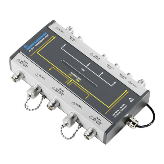
Page 35: Legend For Front Panel View
R&S FS-Z10 Putting into Operation Legend for Front Panel View Number Description RF OUT 1; Connect to the RF input of analyzer A. TRIG OUT 1; Connect to the trigger input of analyzer A TRIG IN; Connect to the “NOISE SOURCE CONTROL” output of analyzer A. TRIG OUT 3;... -
Page 36: Unpacking The R&S Coherence Box
R&S FS-Z10 Putting into Operation Unpacking the R&S Coherence Box 1. Remove the instrument from its packaging (see separate unpacking instruction) and check the equipment for completeness using the delivery note and the accessory lists for the various items. 2. Check the instrument for any damage. If there is damage, immediately contact the carrier who delivered the instrument. -
Page 37: Installing The Software
R&S FS-Z10 Installing the Software 4 Installing the Software Hardware and Software Requirements PC Hardware Requirements Minimum Recommended 1 GByte 2 GByte Harddisc 15 MByte free space 50 MByte free hard disc space Monitor VGA monitor (640x480) SVGA color monitor, resolution 800x600 or better IEEE Bus Optional Optional... -
Page 38: Install Microsoft .Net Framework Version 2.0
R&S FS-Z10 Installing the Software 3. Make sure that VISA. is properly installed on your system. Details on each installation step can be found in the following sections. 4.2.1.1 Install Microsoft .NET Framework Version 2.0 To install the coherence unit remote software, Microsoft .NET Framework 2.0 or a later version must be installed. -
Page 39: Installing The Coherence Unit Remote Software
R&S FS-Z10 Installing the Software Installing the Coherence Unit Remote Software 4.2.2 After installing all required components, the Coherence Unit software can be installed. In order to start this installation process: 1. Navigate to the installation location (typically the CD ROM drive). 2. -
Page 40: Setting Up A Measurement
R&S FS-Z10 Setting up a Measurement 5 Setting up a Measurement To achieve best accuracy, it is advisable to calibrate the cables used to connect the DUT to the coherence unit before starting the actual measurement. For this reason, the coherence unit remote software provides a calibration mode and a measurement mode. -
Page 41: Measurement Mode
R&S FS-Z10 Setting up a Measurement Measurement Mode The measurement mode denotes the actual test mode. The signal differences which were measured during calibration mode will be compensated automatically. To perform a measurement connect the instruments as shown in the following figure: Figure 5-2: Cable Connections for measurement mode Manual 1173.0008.32 - 03... -
Page 42: Performing A Measurement
R&S FS-Z10 Performing a Measurement 6 Performing a Measurement Perform Calibration The first step is to calibrate your cables using the Calibration Mode. You may also perform a measurement without calibration, though the result accuracy will be lower. Perform the following steps to do the calibration: 1. -
Page 43: Use Of External Attenuators
R&S FS-Z10 Performing a Measurement 2. Press the "RUN SGL" button for a single measurement or the "RUN CONT" button for continuous measurements. 3. View the results of your measurement as graph or result list (switch views via "Display" softkey) or watch the results of the last measurements as results vs. time (press the “Meas Results”... - Page 44 R&S FS-Z10 Performing a Measurement Figure 6-1: Measurement setup including external attenuation. However, these attenuators cause additional unwanted phase-, timing- and gain differences which need to be taken into account during the calibration process (see Figure 6-2). Manual 1173.0008.32 - 03...
- Page 45 R&S FS-Z10 Performing a Measurement Figure 6-2: Calibration setup including external attenuation. Manual 1173.0008.32 - 03...
- Page 46 R&S FS-Z10 Performing a Measurement Some difficulties arise due to the fact that the external attenuation only attenuates the Measurement Part of the signal (see Figure 2-3: Coherence Measurement Signal path) but not the Reference Part (see Figure 2-2: Coherence Reference Signal path). As a result of this the reference part of the signal might have a significantly higher level than the measurement part.
- Page 47 R&S FS-Z10 Performing a Measurement Figure 6-4: Signal structure of a calibration sweep with compensated external attenuation. The FS-Z10 Remote Software provides the possibility of either configuring the external attenuation values manually, or of detecting them automatically (see chapter 8.1). However, the automatic detection is only possible during the calibration process and not during the measurement.
-
Page 48: Explanation Of The Results
R&S FS-Z10 Explanation of the Results 7 Explanation of the Results Result Overview Figure 7-1: Description of the Result Overview The result overview provides a summary of the most relevant measurement settings and results. The following values are displayed: Value Description 1. -
Page 49: Capture Buffers View
R&S FS-Z10 Explanation of the Results Capture Buffers View Switch to Capture Buffers view. Remote: CALC:FEED ‘PVT’ The Capture Buffers View shows the power vs. time for both paths. Screen A directly plots the power values received from Analyzer A while Screen B performs some compensations before plotting the data. -
Page 50: Meas Results View
R&S FS-Z10 Explanation of the Results Meas Results View Switch to Meas Results view. Remote: CALC:FEED ‘RVT’ The Meas Results View contains a graphical display of all measurement results such as Phase Difference, Timing Difference, Gain Difference and DVM, plotted over time. The graphs are reset on each new continuous sweep start. -
Page 51: Result List View
R&S FS-Z10 Explanation of the Results Result List View Switch back and forth between Graph and List view. Remote: Not available. The screenshot shown in the following figure shows the result list after having performed a calibration and a measurement. Figure 7-2: Result list The column to the right shows the results of the calibration and the column to the left shows the results of the current measurement. -
Page 52: Logfile In Continuous Mode
R&S FS-Z10 Explanation of the Results The accuracy of the result displayed in the Result List View can be improved by activating the High Accuracy Mode (for details see chapter 9.3). Logfile in Continuous Mode If you are running the software in continuous mode, a logfile will be created. The file will be stored under "<Program Folder>\Logfile.txt"... -
Page 53: Settings
R&S FS-Z10 Settings 8 Settings The SETTINGS softkey opens the Settings dialog which contains two tabs: Primary and Advanced. To see the content of the tabs as shown below, click one of the tabs. The Settings dialog is only available if all connected instruments have been identified before. -
Page 54: Primary Settings
R&S FS-Z10 Settings Primary Settings Figure 8-1: Primary settings window (all fields are dimmed because no instruments are connected) The hardware setup of the connected instruments determines which fields will be available and which will be unavailable. Frequency Specifies the Center Frequency of the signal to be measured. The maximum frequency depends on the hardware configuration of your instruments. - Page 55 R&S FS-Z10 Settings Sampling Rate Specifies the Sampling Rate to be used for the measurement. This setting will automatically adjust the maximum signal bandwidth to be measured. Check the manuals of your spectrum analyzers for details about the available bandwidth as a function of the sampling rate used.
- Page 56 R&S FS-Z10 Settings When the Auto Level check box is enabled, the coherence unit remote software will measure the reference level automatically at the start of each measurement sweep. This ensures that the reference level is always set at the ideal level for obtaining accurate results, but will slightly increase the required measurement time.
- Page 57 R&S FS-Z10 Settings External Attenuation The FS-Z10 Remote Software provides the possibility to compensate external attenuation used in your test setup, which should not be part of the measurement results. An additional trigger cable from the “TRIG OUT 3”-output of the FS-Z10 to the “INST TRIG IN”-input of the generator needs to be connected if external attenuation is being used.
- Page 58 R&S FS-Z10 Settings Hardware Settings The Hardware Settings configure the instrument connections. Clicking one of the buttons in the VISA RSC column opens the "Instrument Connection Configuration" dialog. Remote: CONF:ADDR1 ‘TCPIP::192.168.0.1’ Remote: CONF:ADDR2 ‘GPIB::28’ Remote: CONF:ADDR3 ‘GPIB::20’ Manual 1173.0008.32 - 03...
-
Page 59: Advanced Settings
R&S FS-Z10 Settings Advanced Settings Figure 8-2: Advanced settings window Auto Level Tracktime Auto Level Tracktime specifies the sweep time used for the auto level measurements. This settings is important for signals with varying signal power (e.g. bursted signals). Make sure that this time is long enough to capture the signal level maximum. Remote: POW:AUTO:TIME 100ms Manual 1173.0008.32 - 03... - Page 60 R&S FS-Z10 Settings El. Attenuation El. Attenuation specifies the electrical attenuation to be applied to the input RF signal. The hardware setup of your instruments determines whether electrical attenuation is available. The attenuation may be set manually or automatically. Remote: INP:EATT2:AUTO OFF Remote: INP:EATT2:STAT ON Remote: INP:EATT2 5dB Preamplifier...
- Page 61 R&S FS-Z10 Settings In order to get the correct number of valid signal samples specified in the Capture Length setting, a certain overhead of samples must be captured. The number of overhead samples necessary depends on the timing difference of the two test signals. The higher the expected timing difference is, the higher the Capture Length Overhead should be set.
-
Page 62: Setup Submenu
R&S FS-Z10 Setup Submenu 9 Setup Submenu Switches to the Setup submenu. The setup menu contains hardware-dependant settings and the R&S Support Button. A detailed description of the Setup-Submenu-entries will be given in the following chapters. Configure Instrument Connections In order to communicate with the instruments, the Rohde & Schwarz analyzers and the signal generator must be connected with the PC using either an IEEE/IEC bus or LAN connection. -
Page 63: Identify Instruments
R&S FS-Z10 Setup Submenu version 3.65 or later) LAN bus system using Host address as TCP/IP address or RSIB a Rohde & Schwarz- computer name. protocol specific protocol Contact your local IT support if you are not (supported with all sure what to enter here. -
Page 64: How To Select A High Accuracy File
R&S FS-Z10 Setup Submenu The Coherence Unit Software provides the opportunity to use an optional High Accuracy Mode. This mode takes hardware characteristics of a specific FS-Z10 into account and therefore leads to improved overall accuracy of the results. The properties of your specific device can be found in the form of a “.dat”-file which can be downloaded from the Rohde&Schwarz website (see chapter 9.3.2). - Page 65 R&S FS-Z10 Setup Submenu 5. Select "Device Specific Data" and click OK 6. Click the high-accuracy data link 7. Enter the device-specific serial number of your coherence unit Make sure that your high accuracy file is always up-to-date. You need to download a new file if your coherence unit has been serviced by Rohde &...
-
Page 66: R&S Support
R&S FS-Z10 Setup Submenu R&S Support This button automatically stores to file the current settings of the software as well as the currently available IQ-data. The R&S Support button creates the three files “FSZ10_SupportFile_Settings.XML”, “FSZ10_SupportFile_IQData_A.txt” and “FSZ10_SupportFile_IQData_B.txt” in the program installation folder. In case of a support request these files should be sent to Rohde&Schwarz to make processing of the request as fast as possible. -
Page 67: File Submenu
R&S FS-Z10 File Submenu 10 File Submenu Opens the file menu. 10.1 Store or Restore General Settings Store current general settings to file. Remote: MMEM:CUN:STOR:SETT ‘C:\Z10-Data\MySettings.XML’ Restore general settings from file. Remote: MMEM:CUN:LOAD:SETT ‘C:\Z10-Data\MySettings.XML’ The FS-Z10 Remote Software offers the possibility of saving and recalling the configuration of the General Settings menu. -
Page 68: Export Of Iq-Data
R&S FS-Z10 File Submenu Restore calibration information from a previously created file. Remote: MMEM:CUN:LOAD:CAL ‘C:\Z10-Data\ MyCalData.CAL’ Another feature of the FS-Z10 Remote Software is the possibility to store and restore calibration data. This can, for example, be very useful when performing measurements on multiple center frequencies or multiple sample rates, since the calibration step requires different cable connections to the actual measurement. - Page 69 R&S FS-Z10 File Submenu < For binary format, data is expected as 32-bit floating point data, Little Endian format (also known as LSB Order or Intel format). (Example: 0x1D86E7BB in hexadecimal notation will be decoded to U7.0655481E-3.) The data order can be either IQIQIQ or II..IQQ..Q. <...
-
Page 70: Remote Control
R&S FS-Z10 Remote Control Remote Control 11.1 Description of commands This section specifies all the remote control commands specific to the FS-Z10 Remote Control Software. Only those commands provided for this option are specified. For details of remote control commands provided by the instruments used please refer to the corresponding user manuals. - Page 71 R&S FS-Z10 Remote Control Indentations: The different levels of the SCPI command hierarchy are represented in the table by means of indentations to the right. The lower the level, the further the indentation to the right. Please note that the complete notation of the command always includes the higher levels as well.
- Page 72 R&S FS-Z10 Remote Control If parameter FULL is selected, full screen is displayed, in the case of SPLit, split screen is displayed. Key words in square brackets can be omitted when composing the header. The full command length must be accepted by the instrument for reasons of compatibility with the SCPI standards.
- Page 73 R&S FS-Z10 Remote Control This keyword is provided for commands the parameters of which consist of a binary data block. Manual 1173.0008.32 - 03...
-
Page 74: Calculate Subsystem
R&S FS-Z10 Remote Control 11.2 CALCulate Subsystem List of commands CALCulate<1..4>:FEED[?] CALCulate<1..4>:FEED[?] Change the displayed result type. Currently “Power vs. Time” and “Results vs. Time” are available. The suffix can be ignored. Example "CALC:FEED ‘RVT’" Select the “Results vs. Time” display. Parameters ‘PVT’... -
Page 75: Configure Subsystem
R&S FS-Z10 Remote Control 11.3 CONFigure Subsystem The CONFigure subsystem contains commands for configuring complex measurement tasks. The CONFigure subsystem is closely linked to the functions of the FETCH subsystem, where the measurement results of the measurements are queried. List of commands CONFigure:ADDRess<1|2|3>[?] CONFigure:CUNit:CGAin[?] CONFigure:CUNit:CLOVerhead[?]... - Page 76 R&S FS-Z10 Remote Control CONFigure:CUNit:CGAin[?] Activates or deactivates gain compensation of capture buffer B. Example "CONF:CUN:CGA ON" Activates gain compensation. Parameters ON|OFF Characteristics *RST value: OFF SCPI: device-specific CONFigure:CUNit:CLOVerhead[?] Configures the capture length overhead. The number of samples captured from the analyzers for each measurement depends on this setting.
- Page 77 R&S FS-Z10 Remote Control Parameters ON|OFF Characteristics *RST value: OFF SCPI: device-specific CONFigure:CUNit:CTIMing[?] Activates or deactivates timing compensation of capture buffer B. Example "CONF:CUN:CTIM ON" Activates timing compensation. Parameters ON|OFF Characteristics *RST value: OFF SCPI: device-specific CONFigure:CUNit:EXTatten:AUTO[?] Activates or deactivates the automatic detection of the external attenuation used during the calibration process.
- Page 78 R&S FS-Z10 Remote Control CONFigure:CUNit:EXTatten<1|2>[?] Configures the expected external attenuation for each of the two signal-paths. The suffix <1|2> is used to select analyzer A or B. This setting is only available if automatic detection of external attenuation is disabled. This option is not available if a SMIQ is used as reference generator.
- Page 79 R&S FS-Z10 Remote Control Parameters ON|OFF Characteristics *RST value: not affected by *RST SCPI: device-specific CONFigure:CUNit:CCOunt [?] Configures the number of averages used for the calibration. Example "CONF:CUN:CCO 10" Set the number of calibration averages to 10. Parameters Numeric value Characteristics *RST value: 15 SCPI: device-specific...
-
Page 80: Fetch Subsystem
R&S FS-Z10 Remote Control 11.4 FETCh Subsystem List of commands FETCh:CUNit:DVM? FETCh:CUNit:GDIFf? FETCh:CUNit:HACNo? FETCh:CUNit:PDIFf? FETCh:CUNit:SERNo? FETCh:CUNit:TDIFf? FETCh:CUNit:DVM? Returns the difference vector magnitude for the last measurement or of the last calibration. The result unit is dB. Example "FETC:CUN:DVM? MEAS" Returns the DVM calculated at the last measurement process. Parameters [MEAS]|CAL Characteristics... - Page 81 R&S FS-Z10 Remote Control SCPI: device-specific FETCh:CUNit:HACNo? Returns the high accuracy service number corresponding to the currently selected high accuracy file as string. Example "FETC:CUN:HACN?" Returns the current high accuracy service number. Characteristics *RST value: - SCPI: device-specific FETCh:CUNit:PDIFf? Returns the measured phase difference of the last measurement or of the last calibration.
- Page 82 R&S FS-Z10 Remote Control Characteristics *RST value: - SCPI: device-specific FETCh:CUNit:TDIFf? Returns the measured timing difference of the last measurement or of the last calibration. The result unit is seconds. Example "FETC:CUN:TDIF? CAL" Returns the timing difference received at the last calibration process. Parameters [MEAS]|CAL Characteristics...
-
Page 83: Initiate Subsystem
R&S FS-Z10 Remote Control 11.5 INITiate Subsystem List of commands INITiate:CABLecal INITiate[:IMMediate] INITiate:REFResh INITiate:CABLecal Starts a new calibration sequence (RUN SGL). If a measurement sequence is already in progress the command will have no effect. Make sure that your cables are connected correctly before starting the calibration. - Page 84 R&S FS-Z10 Remote Control INITiate:REFResh Recalculates all results using the current settings and the currently available capture buffer. No new data will be queried from the instruments. Example "INIT:REFR" Refreshes all results using the currently available data. Characteristics *RST value: - SCPI: device-specific Manual 1173.0008.32 - 03...
-
Page 85: Input Subsystem
R&S FS-Z10 Remote Control 11.6 INPut Subsystem List of commands INPut:ATTenuation<1|2>:AUTO[?] INPut:ATTenuation<1|2>[?] INPut:EATT<1|2>:AUTO[?] INPut:EATT<1|2>:STATe[?] INPut:GAIN<1|2>:AUTO[?] INPut:GAIN<1|2>:STATe[?] INPut:FILTer:YIG<1|2>[:STATe][?] INPut:ATTenuation<1|2>:AUTO[?] Activates or deactivates automatic setting of the RF attenuation depending on the current reference level for each of the two analyzers. The suffix <1|2> is used to select analyzer A or analyzer B. - Page 86 R&S FS-Z10 Remote Control Characteristics *RST value: 10 dB SCPI: device-specific INPut:EATT<1|2>:AUTO[?] Activates or deactivates automatic setting of the electrical attenuation for the selected analyzer. The suffix <1|2> is used to select analyzer A or analyzer B. This setting is only available if supported by the connected analyzer hardware. Example "INP:EATT2:AUTO OFF"...
- Page 87 R&S FS-Z10 Remote Control INPut:EATT<1|2>[?] Configures the electrical attenuation value to be used for the selected analyzer. The suffix <1|2> is used to select analyzer A or analyzer B. Can only be set if automatic electrical attenuation is deactivated. This setting is only available if supported by the connected analyzer hardware.
- Page 88 R&S FS-Z10 Remote Control INPut:GAIN<1|2>:STATe[?] Activates or deactivates the preamplifier for the selected analyzer. The suffix <1|2> is used to select analyzer A or analyzer B. This setting is only available if supported by the connected analyzer hardware. Example "INP:GAIN2:STAT OFF" Deactivate the preamplifier for analyzer B.
-
Page 89: Instrument Subsystem
R&S FS-Z10 Remote Control 11.7 INSTrument Subsystem List of commands INSTrument:IDENtify INSTrument:SELect SAN INSTrument:IDENtify Establishes a hardware connection to all instruments currently configured in the settings menu and queries all relevant instrument properties. Example "INST:IDEN" Identifies all currently connected instruments. Characteristics *RST value: - SCPI: device-specific... -
Page 90: Mmemory Subsystem
R&S FS-Z10 Remote Control 11.8 MMEMory Subsystem List of commands MMEM:CUNit:IQ:FORMat[?] MMEM:CUNit:LOAD:CALib MMEM:CUNit:LOAD:SETTing MMEM:CUNit:STORe:CALib MMEM:CUNit:STORe:IQ MMEM:CUNit:STORe:SETTing MMEM:CUNit:IQ:FORMat[?] Specifies the format used to store the IQ data. The data can either get stored as interleaved data (“I,Q,I,Q, I,Q,I,Q,…”) or in blocks (“I,I,I,I,…,Q,Q,Q,Q,…”). Example "MMEM:CUN:IQ:FORM IQP"... - Page 91 R&S FS-Z10 Remote Control Characteristics *RST value: - SCPI: device-specific MMEM:CUNit:LOAD:SETTing Restores all general settings which have previously been stored to a XML file. Example "MMEM:CUN:LOAD:SETT ‘C:\Temp\MySettings.XML’" Restores all settings from the file “MySettings.XML”. Parameters File-path as string. Characteristics *RST value: - SCPI: device-specific MMEM:CUNit:STORe:CALib Store the current calibration results to a file for later use.
- Page 92 R&S FS-Z10 Remote Control MMEM:CUNit:STORe:IQ Stores the IQ data currently available in the capture buffer to the specified file. The filetype may either be "*.iqw" or “*.dat”. Depending on the file extension the data will be stored as binary data (*.iqw) or as ASCII data (*.dat). Since there are two data streams available, two files will be created each time data gets saved.
-
Page 93: Sense Subsystem
R&S FS-Z10 Remote Control 11.9 SENSe Subsystem List of commands [SENSe]:FREQuency:CENTer[?] [SENSe]:POWer:AUTO[?] [SENSe]:POWer:AUTO:TIME[?] [SENSe]:POWer:AUTO:ZATTallowed [?] Defines if the internal attenuators of the analyzers are allowed to be set to 0dB during the autoleveling-process or not. Example "POW:AUTO:ZATT ON" Allow to set the internal attenuation to 0dB during the autoleveling. Parameters ON|OFF Characteristics... - Page 94 R&S FS-Z10 Remote Control SCPI: conforming [SENSe]:POWer:AUTO[?] Activates or deactivates auto leveling for both analyzers. Example "POW:AUTO OFF" Deactivate auto leveling. Parameters ON|OFF Characteristics *RST value: ON SCPI: device-specific [SENSe]:POWer:AUTO:TIME[?] Configures the sweep time used for autoleveling. If activated autoleveling will be performed prior to each sweep even in continuous mode.
- Page 95 R&S FS-Z10 Remote Control Parameters ON|OFF Characteristics *RST value: OFF SCPI: device-specific [SENSe]:SWEep:SAMPles [?] Configures the number of samples to be captured for a single measurement. Changing this value will also change the capture length in seconds (= sweep time). Example "SWE:SAMP 10k"...
-
Page 96: Trace Subsystem
R&S FS-Z10 Remote Control 11.10 TRACe Subsystem List of commands TRACe<1|2|3|4>:DATA? TRACe<1|2>:IQ:SRATe[?] TRACe<1|2|3|4>:DATA? The return values depend on the currently selected measurement (use the CALCulate:FEED command to select a measurement). The following measurements are available: Capture Buffer: A list of interleaved IQ-data will be returned. The suffix selects either the data from capture buffer A (suffix = 1) or the data from capture buffer B (suffix = 2). - Page 97 R&S FS-Z10 Remote Control Example "TRAC2:DATA?" Returns the Timing Differences displayed in graph B (only applicable if currently in Results vs. Time mode). "TRAC4:DATA?" Returns the DVM values displayed in graph D (only applicable if currently in Results vs. Time mode). Parameters Numeric values as comma separated list Characteristics...
-
Page 98: Index
R&S FS-Z10 Index Index auto level ..........31, 32 external attenuation........33 Capture settings advanced reference level..........32 capture length overhead .......36, 37 RF attenuation..........32 compensation settings ........33 Level settings advanced Configure instrument connections ....38 auto level tracktime ........35 el attenuation ..........
Need help?
Do you have a question about the R&S FS-Z10 and is the answer not in the manual?
Questions and answers