
Subscribe to Our Youtube Channel
Related Manuals for Selec PIC352


Summary of Contents for Selec PIC352
- Page 1 Process Indicator PIC352 OPERATING INSTRUCTIONS Doc. name: OP INST PIC352 OP3023-V01 Selec Controls Pvt. Ltd., India Tel.: +91-22-4141 846 / 452, Fax: +91-22-41418 408 Website: www.selec.com Email: sales@selec.com...
-
Page 2: Table Of Contents
CONTENTS Page no. A) OVERVIEW. 1. Features 2. Ordering information B) SPECIFICATIONS C) INSTALLATION. 1. Safety Information 2. Terminal connections 3. Sensor input wiring 4. Output wiring D) PROGRAMMING. 1. Function menu 2. Key's description 3. Level 0-Input parameters 4. Level 1 Alarm Module (Alarm 1) 5. -
Page 3: Features
Optional Features v Dual 4 digit display v RS485 MODBUS communication v Digital filtering v Compliance - v Sensor break indication v IP65 front panel protection v Sensor error compensation v Programmable parameter lockouts v 90 to 270 VAC/DC supply www.selec.com... -
Page 4: Ordering Information
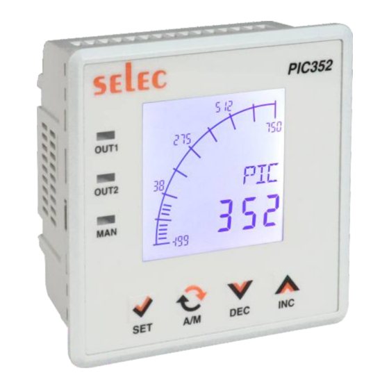
Analog Output Current & Voltage RS485 Slave Communication 1. TECHNICAL SPECIFICATIONS 1. DISPLAY Display PIC352 - 96X96- 4 digit Alphanumeric and 4 digit 7-Seg LCD with Selectable Multicolor Backlight as per user requirements. OUT1, OUT2, MAN (Manual) Led Status Annunciators www.selec.com... -
Page 5: B) Specifications
SPECIFICATION 1. TECHNICAL SPECIFICATIONS 1. DISPLAY Display PIC352 - 96X96- 4 digit Alphanumeric and 4 digit 7-Seg LCD with Selectable Multicolor Backlight as per user requirements. OUT1, OUT2, MAN (Manual) Led Status Annunciators 2. INPUT Thermocouple : J, K, T, R, S, C, E, B, N, L, U, W, Platinel II. - Page 6 100ms (max and independent of baud rate) 6. ENVIRONMENTAL CONDITIONS Operating range 0..55°C Storage range -20..75°C Storage humidity 85% max. RH (non condensing) from 0 to 50°C 7. POWER SUPPLY Power supply 90..270VAC / DC Frequency 50 / 60Hz Power consumption 8VA max www.selec.com...
- Page 7 9. SAFETY AND EMC STANDARDS Compliance As per BS EN 61010 As per BS EN 61326 Panel sealing IP65 WEIGHT : PIC352-11-U-X-1 : 200gms 10. HOUSING : Flame retardant engineering plastic 11. INPUT SENSOR RANGES (for 1°C resolution) Sensor type Range Sensor type Range -200 to 750°C...
-
Page 8: Safety Information
5. The output terminals shall be strictly loaded to the manufacturer specified values/range. MAINTENANCE 1. The equipment should be cleaned regularly to avoid blockage of ventilating parts. 2. Use soft cloth for cleaning. Do not use isopropyl alcohol or any other organic cleaning agent. www.selec.com... - Page 9 3. Push the controller into the panel cutout. Secure the controller in its place by pushing the clamp from the rear side. CAUTION : The equipment in its installed state must not come in close proximity to any heating sources, caustic vapors, oils, steam, or other unwanted process by-products. www.selec.com...
-
Page 10: Terminal Connections
EMC Guidelines : Use proper input power cables with shortest connections and twisted type. Layout of connecting cables shall be away from any internal EMI source. 2. TERMINAL CONNECTIONS PIC352-11-U-C-1 Sensor supply Digital input NPN / PNP 24VDC, 80mA Analog input PIC352-11-U-0-1 www.selec.com... -
Page 11: Sensor Input Wiring
INSTALLATION 3. SENSOR INPUT WIRING PIC352-11-U-X-1 TC - Thermocouple (J, K, T, R, S, C, E, B, N, L, U, W, Platinel II). V - Voltage Input (0 to 10 V DC). mA - Current Input (0 to 20mA DC) RTD - PT100 / PT1000 NOTE : 1) Refer input type selection in level 0 of programming menu. - Page 12 INSTALLATION Fig. 2. Alarm Output - Relay to drive contactor (For single phase) Fig. 3. External Key Connection PIC352-11-U-X-1 PIC352-11-U-X-1 For Relay Drive Contactor Drive This function is available when keys is selected in DIN (Digital input) in level 3 NOTE: Use snubber as shown above to increase life of internal relay of temperature controller.
-
Page 13: Function Menu
PROGRAMMING 1. FUNCTIONS MENU www.selec.com... -
Page 14: Key's Description
NOTE : The unit will auto exit program mode after 30 seconds of inactivity. INDICATIONS AND DISPLAY Process-value (PV) Display the process temperature value. Custom display User selectable display OUT1 Indication for Alarm 1 OUT2 Indication for Alarm 2 Indication for Manual output www.selec.com... -
Page 15: Level 0-Input Parameters
Feed the higher value of the analog Analog Input point 1 to mA / input type input signal. selected. mV / Reverse scaling Display scaling points Analog Input can be reversed. Fixed 1°C resolution for R, S, B type thermocouple. www.selec.com... -
Page 16: Level 1 Alarm Module (Alarm 1)
The controller has programmable high and low set point limit values to restrict the setting range of the set point. Set the limit values so that the temperature set point value cannot be set outside the safe operating area of the process. www.selec.com... -
Page 17: Level 2-Alarm Module (Alarm 2)
SPLL to SPHL (LA Mode) If alarm mode is of f 0.1 to 99.9 (For TC/RTD); Hystersis 0.1 to 99.9 (For Analog Input) TC / RTD: -9.9 to 9.9 Analog Hystersis bias I / P: -9.9 to 99 As per decimal point www.selec.com... - Page 18 : The alarm is turned ON when PV rises above or Falls below a preset value. Ÿ SENSOR BREAK ALARM : Ÿ The alarm is turned ON in case of : A) Measurement value exceeds range B) Sensor reverse condition (applicable for TC/RTD) www.selec.com...
-
Page 19: Level 3-Analog O/P & Special Function Module
-999 To +999 for AIN models decimal point as per selected. OFF,1 to 99 seconds Filter time constant 0.1 to 10.0 for TC / RTD TC / RTD with Rounding display As per decimal Point resolution = 1°C selected For analog input or Analog www.selec.com... - Page 20 All displays are OFF. b. All outputs are OFF i.e.OUT1,OUT2,MAN & LED's are OFF. c. Analog output is limited to the lower range. d. All front keys are disabled. e. Access to configuration enabled. The STND status is preserved on power OFF. www.selec.com...
-
Page 21: Level 4-Communication Module
1. Maximum 32 slave controllers can be connected to the master RS485-RS232 Converter 2. The total cable length should not exceed 500 meters Part no. - AC-RS485-RS232-01 3. Use shielded twisted -pair cables for RS485 connections 4. Use terminators having a resistance of 100ohm (1/2 watt). www.selec.com... -
Page 22: Level 5-Lockout Module
1) IDM Level - IDM should be connected before powering on the unit to enter in IDM level 2) Long press key for 3 sec to exit from IDM mode. Caution : After Downloading, switch of the unit and then remove the IDM www.selec.com... -
Page 23: E) Calibration Certificate
CALIBRATION CERTIFICATE Model No : PIC352-11-U-X-1 Claimed Accuracy : ± 0.1 % of full scale ±1 digit (After 20min warmup time) Standard used for calibration of the product is traceable to NABL The calibration of this unit has been verified at the following values:...
Need help?
Do you have a question about the PIC352 and is the answer not in the manual?
Questions and answers