Advertisement
Quick Links
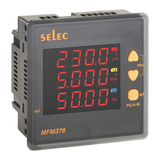
MFM376 SERIES
selec
Operating Instructions
96 x 96
SPECIFICATIONS
DISPLAY
3 Row of 4 Digits
7 Segment LED Display 0.49 inch Height Digit
Integrated with parameter Units
WIRING INPU
T
3 Ø 4 wire, 3 Ø - 3 wire, 2 Ø - 3 wire and Ø -
-
1
2 wire
(R/Y/B Programmable)
RATED INPUT VOLTAGE
11 to 300V AC (L-N) ; 19 to 519V AC (L-L)
Installation Category
III
(600V)
FREQUENCY RANGE
45-65 Hz
RATED INPUT CURRENT
Nominal 5A AC (Min-14mA, Max-6A)
BURDEN
0.5VA@5A per phase
CT PRIMARY
1A / 5A to 10,000A (Programmable for any value)
Note :
1A to 10,000A if CT secondary is 1 else
5A to 10,000A
CT SECONDARY
1A or 5A (programmable)
PT PRIMARY
100V to 500kV (Programmable for any value)
PT SECONDARY
100 to 500V (Programmable for any value)
DISPLAY UPDATE TIME
1 sec. for all parameters
DISPLAY SCROLLING
Auto / Manual / Default
POWER CONSUMPTION
Less than 8VA
ENVIRONMENTAL CONDITIONS
- Indoor use
- Altitude of up to 2000 meters
- Pollution degree
II
Temperature :
Operating : -10 C to 55 C
°
°
Storage : -20 C to 75 C
°
°
Humidity
: Up to 85% non-condensing
MOUNTING :
Panel mounting
WEIGHT
MFM376-230V AC : 260gms
MFM376-C
: 230gms
OUTPUT
Pulse Output
:
Voltage range : External 24V DC max.
Current capacity : 100 mA max
±
Pulse Width :
100ms 5ms.
ORDER CODE INFORMATION
Product
Supply
Certification
MFM376-230VAC
240V AC, 20%, 50/60Hz
±
40V - 270V DC,
MFM376-C
85V - 270V AC, 50/60Hz
Installation Category III
ACCURACY
Measurement
Accuracy
Voltage V
±0.5% of Full scale
L-N
Voltage V
±
0.5% of
Full scale
L-L
Current
±0.5% of Full scale
±0.1%
Frequency
For L-N Voltage >20V,
For L-L Voltage >35V
Active Power
1%
Apparent power
1%
Reactive Power
1%
Power Factor
±0.01
Active Energy
Class 1
Reactive Energy
Class 1
Apparent Energy
Class 1
RESOLUTION :
kWh /
PT
Ratio
x
kVAh /
Pulse
CT Ratio
kVArh
<40
0.01K
0.01K
<400
0.1K
0.1K
<
40
00
1K
1K
<
40
000
0.01M
0.01M
<
40
0000
0.1M
0.1M
4000000
1M
1M
Note : a) For voltage, current and power resolution is
automatically adjusted
b) For power factor resolution is 0.001
c) • Blinks indicating accumulation of energy, if load
is connected on any one phase of 3 Phase.
SAFETY PRECAUTIONS
All safety related codifications, symbols and
instructions that appear in this operating manual or on
the equipment must be strictly followed to ensure the
LISTED
safety of the operating personnel as well as the
instrument.
If the equipment is not used in a manner specified by the
manufacturer it might impair the protection provided by the
equipment.
Do not use the equipment if there is any mechanical
damage.
Ensure that the equipment is supplied with correct
voltage.
CAUTION :
1. Read complete instructions prior to installation and
operation of the unit.
2. Risk of electric shock.
3. The equipment in its installed state must not come in
close proximity to any heating sources, oils, steam,
caustic vapors or other unwanted process by products.
WIRING GUIDELINES
WARNING :
1. To prevent the risk of electric shock, power supply to the
equipment must be kept OFF while doing the wiring
arrangement.
2. Wiring shall be done strictly according to the terminal
layout. Confirm that all connections are correct.
3. Use lugged terminals.
4. To reduce electromagnetic interference use of wires with
adequate ratings and twists of the same in equal size shall
be made with shortest connections.
5. Layout of connecting cables shall be away from any
internal EMI source.
6. Cable used for connection to power source, must have a
2
cross section of 0.5mm to 2.5mm
Thesewires shall have current carryingcapacityof 6A.
INT
7. Copper cable should be used
(Stranded or Single core cable).
8. Before attempting work on device, ensure absence of
0.001K
voltages using appropriate voltage detection device.
0.01K
INSTALLATION GUIDELINES
0.1K
CAUTION :
1. This equipment, being built-in-type, normally becomes a
1K
part of main control panel and in such case the terminals
0.01M
do not remain accessible to the end user after installation
and internal wiring.
0.1M
2. Conductors must not come in contact with the internal
circuitry of the equipment or else it may lead to a safety
hazard that may in turn endanger life or cause electrical
shock to the operator.
3. Circuit breaker or mains switch must be installed
between power source and supply terminals to facilitate
power 'ON' or 'OFF' function. However this switch or
breaker must be installed in a convenient position
normally accessible to the operator.
4.
Before disconnecting the secondary of the external
current transformer from the equipment, make sure that
the current transformer is short circuited to avoid risk of
electrical shock and injury.
5. The equipment shall not be installed in environmental
conditions other than those mentioned in this manual.
6
. The equipment does not have a built-in-type fuse.
Installation of external fuse of rating 275V AC /
electrical circuitry
/ battery
is highly recommended.
MECHANICAL INSTALLATION
For installing the meter
1. Prepare the panel cutout with proper dimensions
shown below.
2
. Push the meter into the panel cutout. Secure the
in its place by fitting the clamp on the rear side. fit
clamps on both sides in diagonally opposite location for
optimum fitting.
3. For proper sealing, tighten the screws evenly with
required torque.
Outline
Dimensions
99
99
3
MAINTENANCE
1. The equipment should be cleaned regularly to avoid
blockage of ventilating parts.
2. Clean the equipment with a clean dry or damp cloth.
Do not use any cleaning agent other than water.
TERMINAL CONNECTIONS
PULSE
OUTPUT
L1
L2
2
0
( 20 to 14AWG ; 75 C(min)).
L3
N
S1
S2
S1
I
1
PULSE
RS485
OUTPUT
L1
L2
L3
N
S1
S2
S1
I
1
0.5
Amp for
Doc. name : OP INST MFM376 SERIES OP506-V02(Page 1 of 4)
a
s
meter
Panel cutout
Dimensions
(in mm)
(in mm)
90.5
49
L
CONNECTION DIAGRAM
L
O
A
D
S2
S1
S2
N
V1
V2
V3
I 2
I 3
CONNECTION DIAGRAM
L
O
A
D
S2
S1
S2
N
V1
V2
V3
I 2
I 3
Advertisement

Subscribe to Our Youtube Channel
Related Manuals for Selec MFM376 Series


Summary of Contents for Selec MFM376 Series
- Page 1 Amp for Pulse Output Voltage range : External 24V DC max. electrical circuitry / battery is highly recommended. Current capacity : 100 mA max ± Pulse Width : 100ms 5ms. Doc. name : OP INST MFM376 SERIES OP506-V02(Page 1 of 4)
- Page 2 1 be displayed. 1P2W-R, 1P2W-Y, 1P2W-B screen neutral voltage, current and power factor. 1P2W Marked values are only valid for MFM376-C. Doc. name : OP INST MFM376 SERIES OP506-V02(Page 2 of 4)
- Page 3 Reset Maximum Demand Auxillary Interrupts 30102 0x66 Integer 40022 0x16 Reset Run Hour Reset Run Hour Total Harmonic Distortion(THD) Integer 40023 0x17 Reset Interrupts Count Reset Auxillary Interrupt Count Doc. name : OP INST MFM376 SERIES OP506-V02(Page 3 of 4)
- Page 4 Navi Mumbai - 400 710, INDIA. Tel. No. : +91-22-41 418 419/430 | Fax No. : +91-22-28471733 Toll free : 1800 227 353 (BSNL/MTNL Subscribers only) Website : www.selec.com | Email : sales@selec.com Doc. name : OP INST MFM376 SERIES OP506-V02(Page 4 of 4)
Need help?
Do you have a question about the MFM376 Series and is the answer not in the manual?
Questions and answers