Advertisement
Available languages
Available languages
Advertisement
Chapters

Related Manuals for Geotech MINI TILLER Series

Summary of Contents for Geotech MINI TILLER Series
- Page 1 MANUALE PER L’UTENTE MOTOZAPPA - serie piccola...
- Page 2 Introduzione Grazie per aver acquistato la presente macchina. Questa tipologia di motozappa è caratterizzata da peso leggero e volume ridotto. Presenta, inoltre, numerose funzionalità e un elevato rendimento. Si presta all’uso in montagna, in collina, su terreni coltivati, in giardini, orti e serre. Tra le principali funzioni ci sono fresatura, assolcatura e trasporto.
-
Page 3: Table Of Contents
Capitolo 1 Istruzioni di sicurezza e adesivi ....................3 1、Istruzioni di sicurezza ........................3 2、Adesivi infromativi sulla sicurezza ....................7 Capitolo 2 Specifiche tecniche principali ....................10 Capitolo 3 Assemblaggio e modalità d’uso ....................12 1、Assemblaggio ..........................12 2、Controlli regolari ..........................13 3、Regolazioni ............................ -
Page 4: Capitolo 1 Istruzioni Di Sicurezza E Adesivi
Capitolo 1 - Istruzioni di sicurezza e adesivi 1. Istruzioni di sicurezza 1. Formazione a) Leggere attentamente le istruzioni. Familiarizzare coi comandi e la modalità corretta di utilizzo del macchinario. b) Non permettere mai ai bambini o a persone che non conoscono le istruzioni d’uso di utilizzare il macchinario. - Page 5 caldo; - In caso di fuoriuscita di benzina, non tentare di avviare il motore, ma spostare la macchina dall’area in cui si è verificata la fuoriuscita ed evitare qualsiasi tipo di accensione fino a quando i vapori della benzina non si saranno dissipati. - Sostituire il tappo del serbatoio e del contenitore del carburante se necessario;...
- Page 6 l) Arrestare il motore: - Ogniqualvolta si abbandona la macchina; - Prima di fare rifornimento; m) Ridurre la velocità durante l’arresto del motore e, nel caso in cui sia provvisto di valvola di arresto, chiudere l’alimentazione del carburante dopo aver concluso il lavoro; n) Non trasportare persone con la motozappa.
- Page 7 all’aperto. 5. Informazioni importanti sull’utilizzo della motozappa a) L’utente deve leggere il presente manuale prima di usare la macchina e rispettare le istruzioni relative alla manutenzione ed eventuale regolazioni. Prima di usare la macchina: b) Usare carburante pulito. Assicurarsi che il motore sia spento e che si trovi in un ambiente ben ventilato durante il rifornimento.
-
Page 8: 2、Adesivi Infromativi Sulla Sicurezza
2. Adesivi informativi sulla sicurezza 1. La marmitta raggiunge temperature elevate. Non toccare la motozappa se è in funzione o se è stata spenta da poco. 2. Quando la motozappa è in funzione, prestare attenzione alle parti rotanti. Non posizionarsi troppo vicino alla macchina al fine di prevenire lesioni. - Page 9 3. Tenere il serbatoio dell’olio a distanza da fiamme e fumo. 4. Assicurarsi che la macchina sia in posizione stabile prima di iniziare a usarla. Leggere attentamente il manuale d’istruzioni.
- Page 10 5. Rispettare le tempistiche per il rifornimento di carburante. 6. Prestare attenzione ai segnali di avvertenza...
-
Page 11: Capitolo 2 Specifiche Tecniche Principali
Capitolo 2 - Specifiche tecniche principali Modello PGT 900 Parametro Elementi 170F Modello motore Motore Potenza nominale 3600 Velocità nominale Dimensioni(L×W×H) mm 1040×530×830 PESO ( kg) Specifiche Modello trasmissione A ingranaggi (trasmissione interna) componenti Connessione dall’albero alle principali Coassiale diretta motozappa zappe rotativa... - Page 12 Zappe (nr. pezzi) Profondità di lavoro (cm) 15-30 Larghezza di lavoro (cm) 85-100 Velocità di lavoro (m/s) 0.1~0.3 ≥0.04 Efficienza oraria ( hm /h·m) ≤30 Consumo carburante (kg/hm • I dati potrebbero subire variazioni come risultato di migliorie e vengono riportati solo per l’informazione dell’utente, senza effetto vincolante...
-
Page 13: Capitolo 3 Assemblaggio E Modalità D'uso
Capitolo 3 - Assemblaggio e modalità d’uso 1. Assemblaggio Le principali regolazioni sono state eseguite in fabbrica. Tuttavia, prima di cominciare a usare la macchina, sarà necessario fare alcune regolazioni aggiuntive perché funzioni in maniera ottimale. Una volta ricevuta la motozappa, assemblarla come segue: 1. -
Page 14: 2、Controlli Regolari
2. Controlli regolari 1. Controllo carburante ⚫ Collocare il motore in piano. ⚫ Rimuovere l’astina di controllo livello olio e pulirla. ⚫ Inserire l’astina di controllo olio nel foro di passaggio (senza avvitarla). ⚫ Togliere l’astina, controllare il livello dell’olio aiutandosi con la scala graduata. ⚫... -
Page 15: 3、Regolazioni
3. Regolazioni 1. Regolazione altezza manubrio ⚫ AVVERTENZE: al fine di evitare che la macchina si ribalti, collocarla con il motore in piano prima di regolare l’altezza del manubrio (immagine 5). Immagine 4 Immagine 5 ⚫ Allentare il regolatore di altezza, selezionare il foro adeguato, impostare l’altezza del manubrio in base all’altezza dell’operatore e stringere il regolatore di altezza. - Page 16 2. Regolazione profondità di lavoro ⚫ La regolazione in altezza dello sperone consente di controllare la profondità di lavoro della motozappa. Abbassando lo sperone si diminuisce la profondità, sollevando lo sperone si aumenta la profondità. 3. Avviamento motozappa ⚫ Assicurarsi che il cambio sia in folle, premere la leva di sicurezza e avviare la macchina seguendo le istruzioni.
- Page 17 Immagine 6 Immagine 7 ⚫ Controllare che il cavo della frizione sia sufficientemente teso (generalmente il valore del gioco può essere 4-8 mm). Se il cavo si allenta, occorre svitare il dado di bloccaggio, aggiustare il cavo e stringere nuovamente il dado. (immagine 9)
- Page 18 Immagine 8 Immagine 9 5. Cambio velocità ⚫ 4 velocità Retromarcia (-1), Avanzamento (1), In folle (0), Avanzamento (2) ⚫ Modalità cambio marcia 1) Spostare l’interruttore del gas verso sinistra (posizione del minimo) effettuando una rotazione in senso orario. 2) Rilasciare la leva della frizione per innestarla. 3) Cambiare marcia tramite l’apposita leva e stringere la leva della frizione.
-
Page 19: Capitolo 4 Manutenzione
Capitolo 4 - Manutenzione Il funzionamento, la frizione e le variazioni di carico faranno allentare i bulloni e provocheranno danni ad alcune componenti portando al deterioramento della macchina, a una perdita di potenza del motore e a un aumento dei consumi di carburante. Al fine di limitare questo processo, bisogna eseguire regolarmente dei lavori di manutenzione. -
Page 20: 2、Manutenzione Tecnica
2. Manutenzione tecnica 1. Manutenzione prima e dopo ogni utilizzo 1) Prestare attenzione a situazioni insolite (rumori inusuali, surriscaldamento, cedimento bulloneria). 2) Controllare eventuali perdite di olio dal motore, dalla trasmissione e dalla scatola del cambio. 3) Verificare se l’olio nel motore e nella trasmissione è a livello. 4) Rimuovere sporcizia, erba e depositi di olio dalla motozappa. -
Page 21: 3、Programma Di Manutenzione
4. Programma di manutenzione Tempistica Ogni Dopo 8 Ogni 20 Ogni Ogni Ogni 2000 giorn ore con ore o dopo 150 ore 1000 ore o ogni metà del ogni mese o ogni 3 ore o 2 anni carico mesi ogni Descrizione massimo anno... -
Page 22: 4、Rimessaggio
4. Rimessaggio Non riporre mai la macchina con benzina nel serbatoio in uno spazio chiuso con ventilazione scarsa. I vapori della benzina potrebbero entrare in contatto con fiamme libere, scintilla, sigarette e così via. Per un periodo di rimessaggio che supera i 30 giorni, si consiglia di osservare le seguenti indicazioni: 1. -
Page 23: Capitolo 5 Messa A Punto Della Motozappa
Capitolo 5 - Messa a punto della motozappa 1. Registrazione gioco coppia conica Qualora si percepissero dei rumori inusuali provenienti dal gruppo trasmissione, spegnere la macchina ed eseguire le verifiche seguenti: 1. Registrazione del gioco della coppia conica nella scatola del cambio (Immagine 10) ①... - Page 24 0.05-0.15 mm oppure allargare lo spessore e assicurarsi che il gioco assiale del gruppo ingranaggi sia 05-0.15 mm.
-
Page 25: Capitolo 6 Problemi Comuni E Soluzioni
Capitolo 6 - Problemi comuni e soluzioni 1. Risoluzione problemi frizione Problema Cause Soluzioni Leva frizione difettosa Riparare o sostituire Cavi frizione difettosi Sostituire La forcella di innesto non è ben Riposizionare o sostituire posizionata Malfunzionamento frizione Leva del cambio rotta Riparare o sostituire Forcella di innesto danneggiata Sostituire... -
Page 26: 2、Risoluzione Problemi Scatola Cambio
2. Risoluzione problemi scatola cambio Problema Causa Soluzione Togliere i bulloni nella parte posteriore Dadi e bulloni dell’albero Impossibile cambiare dell’albero principale, stringere i dadi marcia principale allentati cilindrici e tornare a fissare i bulloni. Impossibile posizionare Abrasione eccessiva dello Sostituire lo spingidisco correttamente la leva del spingidisco... - Page 27 L’albero principale si sposta; i Stringere i bulloni bulloni di serraggio nella parte posteriore della scatola del cambio sono allentati Leva del cambio deformata Riparare o sostituire la leva del cambio conseguenze funzionamento. Forcella innesto retromarcia Regolare il cavo della leva innesto erosa retromarcia Sostituire forcella innesto retromarcia...
- Page 28 forcella innesto Pulire eventuali residui di sporco che retromarcia si è bloccata impediscono movimento della forcella Albero retromarcia allentato Stringere bulloni nella parte posteriore dell’albero Non si riesce a retromarcia disinnestare la Molla albero per la retromarcia Sostituire la molla retromarcia difettosa Sostituire l’albero per la retromarcia...
-
Page 29: 3、Risoluzione Problemi Sistema Trasmissione
Ingranaggi o leva retromarcia Sostituire deformati o piegati Gioco laterale eccessivo Sostituire gli ingranaggi Rumore eccessivo dovuto all’usura degli proveniente dagli ingranaggi ingranaggi La coppia conica, l’albero per Sostituire la retromarcia e la scatola del cambio non sono ben fissati 3. -
Page 30: 4、Altri Problemi
Perdite di olio consistenti dalla Coppa olio fessurata Sostituire coppa dell’olio Perdite olio dal tappo di Guarnizioni a O (O-ring) Cambiare scarico danneggiate Bullone allentato Stringere La coppa dell’olio presenta un Perdite di olio dalla coppa Saldare o coprire dell’olio piccolo foro 5. -
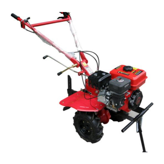
Page 31: Componenti Principali
Componenti principali 1. Leva di sicurezza 2. Stegola manubrio 3. Scatola cambio 4. Motore a benzina 170F 5. Paratia di protezione 6. Organi di traino 7. Sperone 8. Leva cambio 9. Leva retromarcia 10. Leva frizione... - Page 32 Capitolo 7 Eventuali accessori Attached Tools Series Name Unit Application Dry field blades Dry-land cultivation Paddy field wheel Paddy field cultivation 2 piece-4 unit anti-wind knife Wetland farming with too much grass 3 piece-4 unit anti-wind knife Efficient paddy field wheel Paddy field cultivation Flood composite knife Dry-land, paddy field...
- Page 33 Lista ricambi Series Parts Work Site Series Parts Work Site Spark Plug Engine The Filter Engine Elements Stop Switch Engine Kinds Of Spring Engine Gear Box Oil Plug Engine Paper Pad Engine Gear Box Piston Roll Engine Oil Seal, Oil Engine Gear Box Cover, o-Ring Oil Tube...
- Page 34 Sede : Fraz. San Venanzo, 11 - 06049 Spoleto (PG) – Italy Si dichiara che la macchina di propria produzione: Designazione : Motozappa Marca/ Brand : Geotech Modello /Model : PGT 900 Anno di costruzione : 2017 alla quale questa dichiarazione si riferisce, è conforme alle seguenti direttive e norme:...
- Page 35 PGT 900 OWNER´S MANUAL MINI TILLER SERIES...
- Page 36 Introduction Thanks for purchasing this serious products of our company. It will surely attribute your family to better life. This kind of tiller is featured by light weight, small volume, multiple-function and high performance. It is widely applied to mountain, hills areas, dry land, paddy field, fruit garden vegetable garden and greenhouse.
- Page 37 Chapter One Safety Instruction And Labels ..................... 3 1、Safety Instruction ..........................3 2、Safety Labels ............................ 7 Chapter Two Main technical specification ....................10 Chapter Three Installation And Use Methods ................... 12 1、Installation ............................. 11 2、Routine check ..........................13 3、Adjustment Of Mini Tiller ......................14 Chapter Four Maintaining Methods ......................
-
Page 38: Chapter One Safety Instruction And Labels
Chapter One Safety Instruction And Labels 1、Safety Instruction 1. Training a) Read the instructions carefully. Be familiar with the controls and the proper use of the equipment; b) Never allow children or people unfamiliar with these instructions to use the machine. Local regulations can restrict the age of the operator;... - Page 39 area of spillage and avoid creating any source of ignition until petrol vapours have dissipated; - replace all fuel tank and container caps securely; d) Replace faulty silencers; e) Before using, always visually inspect to see that the tools are not worn or damaged. Replace worn or damaged elements and bolts in sets to preserve balance.
- Page 40 shut-off valve, turn the fuel off at the conclusion of working; n) Never load person, when starting at cobbled road、 sidewalk or on the rode, pls keep watch, note the traffic situation in case of the potential dangers! 0) Once abnormal condition happens, immediately close the engine! Look for the reason, vibration is often the beginning of the fault p) When tilling in the hard land, the blades may lowing the ground, be more careful.
-
Page 41: 2、Safety Labels
fuel get in touch with high temperature surface、 rotating parts or electrical components, never add too much oil in order to avoid overflowing, if there is fuel spillage or leakage, dry it up before starting the machine, cover up fuel tank cap and tighten it. In case of fire , storage sites and venues are strictly prohibited fireworks, d) Check whether the bolt is fixed;... - Page 42 2. When the power tiller is working, keep an eye on the rotary parts, do not be too close to the machine to avoid being hurt by the rotary blades. 3, Keep the components of oil box away from fire and smoke. 4.
- Page 43 5. Please refuel in time 6. Please pay attention to warning signs...
-
Page 44: Chapter Two Main Technical Specification
Chapter Two Main technical specification Model PGT 900 Parameter Items 170F Engine model engine Rated power 3600 Rated speed Measurement (L×W×H) mm 1040×530×830 WEIGHT( kg) Rotary Transmission Model(inside Gear drive cultivator transmission) supporting Connection type(from output Coaxial straight-through type parts shaft to blades) Speed (r/min) High gear:135 ;... - Page 45 Blades (pcs) Tilling depth (cm) 15-30 Tilling width (cm) 85-100 operating speed (m/s) 0.1~0.3 ≥0.04 Hourly efficiency( hm /h·m) ≤30 Main fuel consumption (kg/hm * Specifications may change due to improvements, and for reference only, not as the acceptance basis...
-
Page 46: Chapter Three Installation And Use Methods
Chapter Three Installation And Use Methods 1、Installation Before sending, we did the debugging of the Main part . But before you operate it, you still need some check and adjustment, to make it to the fullest use. Since you get the mini tiller, assemble it as follows: 1. -
Page 47: 2、Routine Check
2、Routine check 1. Check engine fuel ⚫ Put the engine in a horizontal position ⚫ Turn out the oil level gauge, Wipe cleanly ⚫ Insert the oil level gauge into the oil passage hole(don’t need to turn in the thread) ⚫... -
Page 48: 3、Adjustment Of Mini Tiller
3、Adjustment Of Mini Tiller 1. Adjust height of handle bar ⚫ Caution: in order to avoid topple over, pls put the engine in flat ground before adjust the height of handle bar.(see picture 5) Picture 4 Picture 5 ⚫ Loosen the regulating handle, choose suitable hole, adjust the height of handle bar to a man’ s waist, and screw the regulating handle 2. - Page 49 ⚫ By adjusting the height of speed control rod, control the depth of rotary tiller, shift down, depth increase; shift up, depth decrease. 3. Start the power tiller ⚫ Put the tiller in neutral gear position , press down handle bar of the emergency power cut off devices, then start the machinery according to this instruction.
- Page 50 ⚫ Confirm the tensity of clutch cable, 4-8mm can be the general degree, out of the scope, you have to loose locknut for adjustment, and tighten up. (see picture 9) picture 8 picture 9 5. Gear shifting ⚫ 4 gear shifting Reverse(-1),Forward(1),Neutral(0),Forward(2) ⚫...
- Page 51 3) Clench the clutch handle bar. Then the power tiller will work on the different gear shifting, and then step on the gas to the new speed as inquired.
-
Page 52: Chapter Four Maintaining Methods
Chapter Four Maintaining Methods Because of running, friction and load change, inevitably produce connection bolt looseness, parts damage phenomenon, which make the system's correct state destroyed, the engine’s power decline, fuel consumption increase, increases the normal use of power tiller. In order to reduce the occurrence of the above situation, we must strictly, regularly do the maintenance work well. -
Page 53: 3、 The Table Of Technical Maintenance (Sign Means The Things You Need Do)
1) Listen and observe the abnormal phenomenon( like abnormal sounds, overheating and bolt failure) 2) Check the Oil leakage status of engine, transmission and walking box. 3) Check the oil lever of engine and transmission, if it is within the limits of oil scale 4) Timely clean the dirt, weeds, oil pollution of the power tiller. - Page 54 Working time Every 20 hours 1000 2000 hours hours later or the hours or hours or every 2 contents under first month the third or per years later month year half load Check the bolt, nut Check and add oil Clean and change oil (first (second...
-
Page 55: 4、Storage
4、Storage Never store the machine with petrol in the fuel tank in a confined area with bad ventilation. Petrol fumes could reach open flames, sparks and cigarettes etc. If the machine is to be stored for a longer period than 30 days, the following methods are recommended. -
Page 56: Chapter Five Debugging Method Of Power Tiller
Chapter Five Debugging Method of Power tiller 1、Debugging method of mesh of bevel gear When the abnormal transmission of mesh of bevel gear of sound is confirmed, stop the machine and check as stipulated below: 1. Clearance adjustment of mesh of angel gear in gear-box ( See Figure 10) ①... - Page 57 3. To ensure the axial clearance of the gearⅡis 0.05-0.15mm. When lateral clearance of mesh of the gear △>0.3mm, we should reduce adjustment padⅠ, meanwhile the axial clearance of gearⅡ is 0.05-0.15mm, or increase the adjustment padⅡ, meanwhile ensure the axial clearance of gear Ⅰis 0.05-0.15mm.
-
Page 58: Chapter Six Common Faults And Methods
Chapter Six Common Faults And Methods 1、Clutch’s faults and methods Phenomenon Reasons Methods Failure of clutch handle bar Fix or replace Failure of clutch cables Change Shifting fork not on the position Readjustment or replace Drop of shift shaft, arm set Fix or replace Clutch failure Break of shift fork... -
Page 59: 2、Gearbox's Faults And Methods
2、Gearbox’s faults and methods Symptom Cause Terms of settlement Dismount the bolts, keys cover at the Failure of fast, slow and Bolts and nuts for the main back of the main shaft, screw the round neutral shift shaft are loose nuts tight, then fix back the bolts and keys cover and screw them tight Failure to shift to the... - Page 60 Main shaft is moving ,the bolts Screw the bolts tight for tightening the cover for the rear of the gear-box body are loose Deformation of shift bar brings Adjust the shift bar or Replace it about interference when you shift Abrasion of reversing fork Re-adjust the cable of reversing shift Replace the reversing fork...
- Page 61 blocked to a standstill Malfunction of spring of the Replace the spring reversing shaft The reversing shaft is bent and Replace the reversing shaft deformed Rear bolts of reversing shaft Screw the reversing shaft are loose The reversing shaft is matching between Replace...
-
Page 62: 3、Faults And Methods Of Walking System
3、Faults and methods of walking system Phenomenon Reasons Methods Gear’s noise too loud excessive wear or wrong fix Reassemble or replace Rotational hairpin of gear Wrong assembling Reassemble Excessive fever Too little lubricating oil Add oil as per demands Oil leak of output shaft sleeve Oil seal is damaged Change oil seal cylindrical surface... -
Page 63: 4、Other Failures
4、Other failures Phenomenon Reasons Methods Plough into rock or other flip Replace it, and pay attention to avoid Break-in of blades crash with hard objects like stone Control cable break-in Long-term wearing Replace... -
Page 64: Chapter Six Products Instruction
Chapter Six Products instruction 1. Emergency power cut off devices 2. Handle bar 3. Gear box 4. 170F gasoline engine 5. Fender 6. Trailer body 7. Drag strut 8. Gear lever 9. Reverse gear handle 10. Clutch handle... - Page 65 Chapter Seven Machine List For Matching Attached Tools Series Name Unit Application Dry field blades Dry-land cultivation Paddy field wheel Paddy field cultivation 2 piece-4 unit anti-wind knife Wetland farming with too much grass 3 piece-4 unit anti-wind knife Efficient paddy field wheel Paddy field cultivation Flood composite knife Dry-land, paddy field...
- Page 66 Easily Damaged Parts List Series Parts Work Site Series Parts Work Site Spark Plug Engine The Filter Engine Elements Stop Switch Engine Kinds Of Spring Engine Gear Box Oil Plug Engine Paper Pad Engine Gear Box Piston Roll Engine Oil Seal, Oil Engine Gear Box Cover, o-Ring Oil Tube...
Need help?
Do you have a question about the MINI TILLER Series and is the answer not in the manual?
Questions and answers