
Related Manuals for RS PRO 2377276

Summary of Contents for RS PRO 2377276
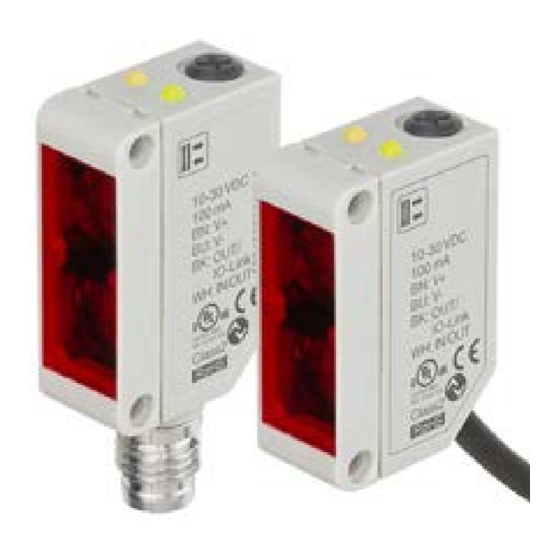
- Page 1 ENGLISH RS PRO IO-Link photoelectric sensor 2377276 and 2377277 Instruction manual...
-
Page 2: Table Of Contents
Table of contents 1. Introduction ..........................5 1.1. Description ............................... 5 1.2. Validity of documentation ..........................5 1.3. Who should use this documentation ......................5 1.4. Use of the product ............................5 1.5. Safety precautions ............................5 1.7. Acronyms ................................6 2. - Page 3 2.5.6.2. Stable OFF .............................. 24 2.5.7. Event configuration ............................ 25 2.5.8. Quality of run QoR ............................25 2.5.9. Quality of Teach QoT ..........................26 2.5.10. Excess Gain ............................... 26 2.5.11. Filter Scaler ..............................26 2.5.12. Mutual interference ..........................26 2.5.13. LED indication ............................27 2.5.14.
-
Page 4: Introduction
Please do not hesitate to make any suggestions for improving this document 1.2. Validity of documentation This manual is valid only for 2377276 and 2377277 photoelectric sensors with IO-Link and until new documentation is published. 1.3. Who should use this documentation This instruction manual describes the function, operation and installation of the product for its intended use. -
Page 5: Acronyms
1.7. Acronyms Input/Output Process Data Programmable Logic Controller Standard Input Output Setpoints IODD I/O Device Description International Electrotechnical Commission Normally Open contact Normally Closed contact Pull load to ground Pull load to V+ Push-Pull Pull load to ground or V+ Quality of Run Quality of Teach UART... -
Page 6: Product
Object and Gap detection are de-central functions dedicated to solve specific sensing tasks. 2.2. Type selection Light type Connection Housing Distance Code Infrare Plug Plastic housing 25 - 200 mm 2377276 Infrare Cable Plastic housing 25 - 200 mm 2377277 RS Components Ltd... -
Page 7: Operating Modes
• Digital output 1: pin 4, black • Digital output 2: pin 2, white The transmission rate of 2377276 and 2377277 sensors is 38.4 kBaud (COM2). Once connected to the IO-Link port, the master has remote access to all the parameters of the... -
Page 8: Process Data
Access to internal parameters allows the user to see how the sensor is performing, for example by reading the internal temperature. Event Data allows the user to get diagnostic information such as an error, an alarm, a warning or a communication problem. -
Page 9: Output Parameters
2.4. Output Parameters Seven sensing functions and 4 application functions can be selected. These values can be independently adjusted and used as source for the Switching Output 1 or 2; in addition to those, an external input can be selected for SO2. After selecting one of these sources, it is possible to configure the output of the sensor with a SCTL55 or an IO-Link master, following the seven steps shown in the Switching Output setup below. -
Page 10: Sensor Front
2.4.1. Sensor front The Background Suppression sensor emits light towards a target and measure the position of the light reflected from the target. If the measured position value is equal to or less than a predefined position for the target, the sensor changes the output state. The measured sensing distance is almost independent of the target colour 2.4.1.1. - Page 11 Two point mode The switching information changes when the distance measured passes the threshold defined in setpoint SP1. This change occurs only with decreasing distance measured. The switching information also changes when the distance measured passes the threshold defined in setpoint SP2.
-
Page 12: Hysteresis Settings
2.4.1.3. Hysteresis Settings The hysteresis can be set automatically or manually for SSC1 and manually only for SSC2. The hysteresis is set in mm for SP1 and SP2. Note: When trimmer is selected, the default hysteresis is Automatic. Automatic hysteresis: Automatic hysteresis will guarantee stable operation for most applications. - Page 13 Symbol Truth table 2-input AND Gate Boolean Expression Q = A.B Read as A AND B gives Q Symbol Truth table 2-input OR Gate Boolean Expression Q = A + B Read as A OR B gives Q Symbol Truth table 2-input XOR Gate Boolean Expression Q = A + B A OR B but NOT BOTH gives Q...
-
Page 14: Timer (Can Be Set Individually For Out1 And Out2)
“Gated SR-FF” function The function is designed to: e.g. start or stop signal for a buffer conveyor dependent on the fill status of the adjacent feeder or receiver conveyor using only two interconnected sensors. Symbol Truth table X – no changes to the 2.4.4. -
Page 15: Turn Off Delay (T-Off)
2.4.4.1.3. Turn Off delay (T-off) The deactivation of the switching output is delayed until after to the time of removal of the target in the front of the sensor, as like shown in the figure below. Presence nce of N.O. Toff Toff Toff... -
Page 16: One Shot Trailing Edge
2.4.4.1.6. One shot trailing edge Similar in function to the one shot leading edge mode, but in this mode the switching output is changed on the trailing edge of the activation as shown in the figure below. This function is Presence of N.O. -
Page 17: Application Functions
2.4.7. Application functions 4 unique application functions can be selected via IO- Link only. • Speed and Length. • Pattern Recognition. • Divider. • Object and Gap Monitoring. 2.4.7.1. Speed and Length This function is designed to monitor the length of an object as well as the speed of a conveyor belt by means of only two interconnected sensors. -
Page 18: Pattern Recognition
b) Select “Sensor role” -> “Trigger Sensor” c) IO-Link Parameter Set-up is finished for the Trigger Sensor 9) Main sensor: (calculates Speed and Length and makes data available Reset the sensor using “Restore factory Settings” (if already performed in point 5 then this can be skipped). Select “Speed and Length”... - Page 19 4) Switch on the power to the sensors 5) Restore the sensors to factory settings using the SCTL55 or IO-Link master. 6) Align the two sensors so the light beams will be detecting the edge of the target at the same time.
-
Page 20: Divider Function
2.4.7.3. Divider function This function allows e.g. the user to set up a number of counts to be performed before changing the output. By default, this value is set to 1 and each activation causes the output to change. When the value is set to a higher value e.g. 10 then the sensor will give output every 10th detection, the sensor will count at the trailing edge of the object. -
Page 21: Object And Gap Monitoring
2.4.7.4. Object and Gap Monitoring This function is designed to monitor that the length of an objects and the gap between the following object on a conveyor belt are within certain limits. The stand alone sensor gives a signal if the size of the object is too small, the objects overlap each other or if the gap between two objects are too small for the following processes. - Page 22 b) Enter the maximum time the Gap will be present in the menu “Object and Gap monitor” -> “Gap maximum time” between 10 … 60 000 ms (default value is 500) ms, e.g. 130 ms. As a help the gap time can be read from the “Object and Gap monitor” -> “Gap time”.
-
Page 23: Sensor Specific Adjustable Parameters
2.5. Sensor Specific adjustable parameters Besides the parameters directly related to output configuration, the sensor also have various internal parameters useful for setup and diagnostics. 2.5.1. Selection of local or remote adjustment It is possible to select how to set the sensing distance by either selecting the “Trimmer Input” or “Teach-by-wire”... -
Page 24: Event Configuration
2.5.7. Event configuration Temperature events transmitted over the IO-Link interface are turned off by default in the sensor. If the user wants to get information about critical temperatures detected in the sensor application, this parameter allows the following 4 events to be enabled or disabled: •... -
Page 25: Quality Of Teach Qot
2.5.9. Quality of Teach QoT The quality of Teach value lets the user know how well the actually the teach procedure was carried out, evaluating the relation between the following parameters: TP2, TP1, Hysteresis and Safe Limits. The value for QoT can vary from 0 … 255 %. The QoT value is updated after every Teach procedure Examples of QoT are listed in the table Quality of Teach values... -
Page 26: Led Indication
2.5.13. LED indication The LED indication can be configured in 3 different modes: Inactive, Active or Find my sensor. Inactive: The LEDs are turned off at all times Active: The LEDs follow the indication scheme in 5.1. Find my sensor: The LEDs are flashing alternating with 2Hz with 50% duty cycle in order to easily locate the sensor. -
Page 27: Teach Procedure By Use Of Sctl55 Or An Io-Link Master
2.6. Teach procedure by use of SCTL55 or an IO-Link master The setpoints can be set-up using a teach procedure, this ensures that the setpoints a set at an optimal value taking into consideration safe limits and hysteresis. 2.6.1. External Teach (Teach-by-wire) NB! This function works in Single point Mode, and only for SP1 in SSC1. - Page 28 Hysteresi Sensor Sensing distance 2) Dynamic teach command sequence Dynamic teach for Single value teach command sequence (Buttons are found in: “Teach-in SSC1” or “Teach-in SSC2” -> “Teach in dynamic SSC1” or “Teach-in dynamic SSC2”) 1. Press “Teach SP1 Start”. 2.
-
Page 29: Two Point Mode Procedure
2.6.2.2. Two point mode procedure 1) Two value teach command sequence: Buttons are found in menu: “Teach-in SSC1” or “Teach in SSC2” -> “Teach-in Two value SSC1” or “Teach-in Two value SSC2” 1. Move the target to the position for SP1 TP1 A. -
Page 30: Windows Mode Procedure
Sensor Sensing distance 2.6.2.3. Windows mode procedure 1) Single value teach command sequence: Buttons are found in menu: “Teach-in SSC1” or “Teach in SSC2” -> “Teach-in Single value SSC1” or “Teach-in Single value SSC2” 1. Move the target to the position for SP1 A. -
Page 31: Foreground Suppression Mode
Hyst Hyst Sensor Sensing window 2.6.2.4. Foreground suppression mode 1) Single value teach command sequence: The button is found in menu: “Teach-in SSC1” or “Teach-in SSC2” -> “Teach-in Single value SSC1” or “Teach-in Single value SSC2” -> “Teach Background” 1. Aim the sensor at the Background A. -
Page 32: Diagnostic Parameters
2.7. Diagnostic parameters 2.7.1. Operating hours The sensor has a built-in counter that logs every hour in which the sensor has been operational. The actual number of operating hours can be read through the SCTL55 or an IO-Link master. 2.7.2. Number of power cycles [cycles] The sensor has a built-in counter that logs every time the sensor has been powered-up. -
Page 33: Wiring Diagrams
NOTE! The temperature measured by the sensor will always be higher than the ambient temperature, due to internal heating. The difference between ambient temperature and internal temperature is influenced by how the sensor is installed in the application. If the sensor is installed in a metal bracket the difference will be lower than if the sensor is mounted in a plastic one. -
Page 34: Operation
5. Operation 5.1. User interface 2377276 and 2377277 sensors are equipped with one yellow and one green LED. SIO and IO-Link mode Green LED Yellow LED Power Detection OFF (stable) SSC1 OFF (Not stable) SSC1 or LEDs disabled ON (Not stable) SSC1... -
Page 35: Iodd File And Factory Setting
6. IODD file and factory setting 6.1. IODD file of an IO-Link device All features, device parameters and setting values of the sensor are collected in a file called I/O Device Description (IODD file). The IODD file is needed in order to establish communication between he SCTL55 or the IO-Link master and the sensor. -
Page 36: Io-Link Device Parameters
7.2. IO-Link Device Parameters 7.2.1. Device Identification Index Parameter Name Acce Default value Data range Data Length Type (Hex) Vendor Name 16 (0x10) RS Components StringT 20 Byte Vendor Text 17 (0x11) www.xxxxxxxxxxxxx StringT 34 Byte (Sensor Product Name 18 (0x12) StringT 20 Byte name) -
Page 37: Ssc Parameters
7.2.3. SSC parameters Index Parameter Name Acce Default value Data range Data Length Type (Hex) 0 = No Channel Teach-In Select 58 (0x3A) Selected UInteger 8 bit 1 = SSC1 (Switching SSC1 l Ch l 1) 2 Teach-In Result 59 (0x3B) 0 = Idle 1 =Success Teach-in State... -
Page 38: Output Parameters
7.2.4. Output Parameters Index Parameter Name Acce Default value Data range Data Length Type (Hex) Channel 1 Setup 64 (0x40) 0 = Disabled output 1 = Stage Mode 1 (0x01) 1 = PNP output UInteger 8 bit PNP output 2 = NPN output 0 = Deactivated 1 = SSC 1 2 = SSC 2... -
Page 39: Sensor Specific Adjustable Parameters
7.2.5. Sensor specific adjustable parameters Index Parameter Name Acce Default value Data range Data Length Type (Hex) 0 = IO-Link Selection of 68 (0x44) 1 = Trimmer input adjust 1 = UInteger 8 bit local/remote Trimmer adjustment SP1 Trimmer value 69 (0x45) 210 mm 23 ... -
Page 40: Application Function
7.2.6. Application Function Index Parameter Name Acce Default value Data range Data Length Type (Hex) 0 = No appliction function selected 1 = Application Function 88 (0x58) 0 = No appliction Speed and Length UInteger 8 bit 2 = Pattern Selector function selected Recognition 3... -
Page 41: Divider
7.2.6.2. Pattern Recognition (cont) Index Parameter Name Acce Default value Data range Data Length Type (Hex) Observation Menu Pattern recognition 97 (0x61) 1 … 20 Time stamp for each Timestamp 1 … 20 UInteger (0x01 … event [ms]. R l ti t t (ti 0 = No Edge 21 …... -
Page 42: Diagnostic Parameters
7.2.7. Diagnostic parameters Index Parameter Name Acce Default value Data range Data Length Type (Hex) Sensor Diagnostics Frontend Failure 209 (0xD1) 0 = OK 0 = OK. 1 = Fail. IntegerT 8 bit EE_MemoryFailur 208 (0xD0) e (during power Memory Failure 1 (0x01) 0 = OK 0 = OK. -
Page 43: Detection Diagram
Dimensions 2377276 2377277 10.6 10.8 10.6 10.8 Receiver Receiver Emitter Emitter Detection diagram Sensing range (inches) 0.16 nsor 0.12 0,08 0.04 Object -0.04 -0.08 -0.12 -0.16 Sensing range (mm) RS Components Ltd... -
Page 44: Sensing Condition
Sensing Condition White background 90% (inches) (Black on white 6%/90%) (Grey on white 18%/90%) (White on white 90%/90%) White background 90% (mm) Installation Hints > 100 mm To avoid interference from inductive Relief of cable strain Protection of the sensing face Switch mounted on mobile carrier voltage/ current peaks, separate the prox. - Page 45 RS Components Ltd Certified in accordance with ISO 9001...
Need help?
Do you have a question about the 2377276 and is the answer not in the manual?
Questions and answers