Fujitsu GENERAL AUHG18LVLB Design & Technical Manual
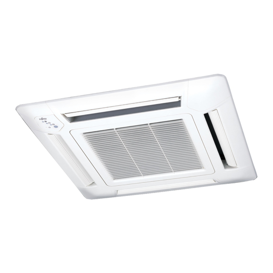
Cassette type
Hide thumbs
Also See for GENERAL AUHG18LVLB:
- Design & technical manual (413 pages) ,
- Design & technical manual (343 pages)

Subscribe to Our Youtube Channel
Related Manuals for Fujitsu GENERAL AUHG18LVLB


Summary of Contents for Fujitsu GENERAL AUHG18LVLB
- Page 1 AIR CONDITIONER Cassette type DESIGN & TECHNICAL MANUAL INDOOR AUHG18LVLB AUHG24LVLA OUTDOOR AOHG18LBCB AOHG24LBCB DR_AU012EG_02 2021.07.15...
- Page 2 Notices: • Product specifications and design are subject to change without notice for future improvement. • For further details, please check with our authorized dealer. Copyright © 2018, 2021 Fujitsu General Limited. All rights reserved.
-
Page 3: Table Of Contents
CONTENTS Part 1. INDOOR UNIT................1 1. Specifications....................2 2. Dimensions....................4 2-1. Models: AUHG18LVLB and AUHG24LVLA ..............4 2-2. Installation space requirement ..................5 3. Wiring diagram ....................6 3-1. Models: AUHG18LVLB and AUHG24LVLA ..............6 4. Capacity table....................7 4-1. Cooling capacity.......................7 4-2. Heating capacity ......................8 5. - Page 4 CONTENTS (continued) Part 2. OUTDOOR UNIT..............37 1. Specifications....................38 2. Dimensions....................39 2-1. Model: AOHG18LBCB ....................39 2-2. Model: AOHG24LBCB ....................40 3. Installation space ..................41 3-1. Models: AOHG18LBCB and AOHG24LBCB..............41 4. Refrigerant circuit ..................44 4-1. Model: AOHG18LBCB ....................44 4-2. Model: AOHG24LBCB ....................45 5. Wiring diagrams ..................46 5-1.
-
Page 5: Part 1. Indoor Unit
Part 1. INDOOR UNIT CASSETTE TYPE: AUHG18LVLB AUHG24LVLA... -
Page 6: Specifications
1. Specifications Cassette Type Inverter heat pump Model name AUHG18LVLB AUHG24LVLA Power supply 230 V ~ 50 Hz Available voltage range 198—264 V 5.20 6.80 Rated Btu/h 17,700 23,200 Cooling 0.90 - 5.90 0.90 - 8.00 Min.—Max. Btu/h 3,100 - 20,100 3,100 - 27,300 Capacity 6.00... - Page 7 Model name AUHG18LVLB AUHG24LVLA Cooling Energy efficiency class Heating (Average) Cooling 5.2 (35°C) 6.8 (35°C) Pdesign Heating (Average) 5.2 (-10°C) 6.0 (-10°C) SEER Cooling 6.20 5.60 kWh/kWh SCOP Heating (Average) 4.20 3.90 Annual energy consumption kWh/a QHE (Average) 1,732 2,151 - 3 - 1.
-
Page 8: Dimensions
2. Dimensions 2-1. Models: AUHG18LVLB and AUHG24LVLA Unit: mm • Cassette grille mounting state 530: Hanging bolt position op view Be sure to leave Service access service access for future service at the designated position. Min. 450 Drain port Drain port Control box Ceiling Side view... -
Page 9: Installation Space Requirement
2-2. Installation space requirement Unit: mm Strong and durable ceiling or more 1,000 1,000 or more or more 1,800 or more Obstruction Floor Maximum height from floor to ceiling (Unit: mm) Standard 2,700 High ceiling 3,000 3-way direction setting: Unit: mm 100 or more* NOTES: •... -
Page 10: Wiring Diagram
3. Wiring diagram 3-1. Models: AUHG18LVLB and AUHG24LVLA - 6 - 3-1. Models: AUHG18LVLB and AUHG24LVLA 3. Wiring diagram... -
Page 11: Capacity Table
4. Capacity table Capacity tables show each of following values calculated based on the outdoor temperature and the indoor temperature, under given Airflow Rate (AFR): For cooling capacity: Total Capacity (TC), Sensible Heat Capacity (SHC), and Input Power (IP) For heating capacity: Total Capacity (TC) and Input Power (IP) 4-1. -
Page 12: Heating Capacity
4-2. Heating capacity NOTE: Values mentioned in the table are calculated based on the maximum capacity. ¢ Model: AUHG18LVLB Indoor temperature °CDB °CDB °CWB 5.01 2.50 4.89 2.55 4.77 2.60 4.65 2.65 4.53 2.71 5.76 2.61 5.62 2.67 5.49 2.72 5.35 2.77 5.21... -
Page 13: Fan Performance
5. Fan performance 5-1. Air velocity distributions ¢ Model: AUHG18LVLB (4-way air outlet) Fan speed Operation mode Ceiling mode Measuring conditions HIGH STANDARD Unit : m/s 0.25 Top view Vertical airflow direction louver: Upward 0.25 0.25 0.25 4 (m) Unit : m/s Side view Vertical airflow direction louver: Upward 0.25... - Page 14 ¢ Model: AUHG18LVLB (3-way air outlet) Fan speed Operation mode Ceiling mode Measuring conditions HIGH STANDARD Unit : m/s 0.25 Top view Vertical airflow direction louver: Upward 0.25 0.25 Unit : m/s Side view Vertical airflow direction louver: Upward 0.25 0.25 Unit : m/s Side view...
- Page 15 ¢ Model: AUHG24LVLA (4-way air outlet) Fan speed Operation mode Ceiling mode Measuring conditions HIGH STANDARD Unit : m/s 0.25 Top view Vertical airflow direction louver: Upward 0.25 0.25 0.25 Unit : m/s Side view Vertical airflow direction louver: Upward 0.25 0.25 Unit : m/s...
- Page 16 ¢ Model: AUHG24LVLA (3-way air outlet) Fan speed Operation mode Ceiling mode Measuring conditions HIGH STANDARD Unit : m/s 0.25 Top view Vertical airflow direction louver: Upward 0.25 0.25 Unit : m/s Side view Vertical airflow direction louver: Upward 0.25 0.25 Unit : m/s Side view...
-
Page 17: Airflow
5-2. Airflow ¢ Model: AUHG18LVLB (Standard ceiling mode) Cooling Fan speed Airflow HIGH QUIET Heating Fan speed Airflow HIGH QUIET - 13 - 5-2. Airflow 5. Fan performance... - Page 18 ¢ Model: AUHG18LVLB (High ceiling mode) Cooling Fan speed Airflow HIGH QUIET Heating Fan speed Airflow HIGH QUIET - 14 - 5-2. Airflow 5. Fan performance...
- Page 19 ¢ Model: AUHG24LVLA (Standard ceiling mode) Cooling Fan speed Airflow HIGH QUIET Heating Fan speed Airflow HIGH QUIET - 15 - 5-2. Airflow 5. Fan performance...
- Page 20 ¢ Model: AUHG24LVLA (High ceiling mode) Cooling Fan speed Airflow 1,030 HIGH QUIET Heating Fan speed Airflow 1,000 HIGH QUIET - 16 - 5-2. Airflow 5. Fan performance...
-
Page 21: Operation Noise (Sound Pressure)
6. Operation noise (sound pressure) 6-1. Noise level curve Ceiling height Outlet directions Measuring conditions Standard 4-way air outlet ¢ Model: AUHG18LVLB Cooling Heating NC-65 NC-65 NC-60 NC-60 NC-55 NC-55 NC-50 NC-50 NC-45 NC-45 HIGH HIGH NC-40 NC-40 NC-35 NC-35 NC-30... -
Page 22: Sound Level Check Point
6-2. Sound level check point Microphone 1.5 m Microphone - 18 - 6-2. Sound level check point 6. Operation noise (sound pressure) -
Page 23: Safety Devices
7. Safety devices Model Type of protection Protection form AUHG18LVLB,AUHG24LVLA Circuit protection Current fuse (PCB*) 250 V, 3.15 A 100 ± 10 °C Activate Fan motor stop Fan motor protection Thermal protection program 95 ± 10 °C Reset Fan motor restart *PCB: Printed Circuit Board - 19 - 7. -
Page 24: External Input And Output
8. External input and output Connector Input Output Remarks CN102 Control input (Operation/Stop) — See external input/output CN103 — Operation status output settings for details. — Fresh-air control output 8-1. External input • “Operation/Stop” mode or "Forced stop" mode can be selected with function setting of indoor unit. •... - Page 25 Circuit diagram example • Contact capacity: DC 24 V or more, 10 mA or Indoor unit more. Connected unit control PCB • *: Make the distance from the PCB to the con- Connector Example: Switch nected unit within 10 m. •...
-
Page 26: External Output
8-2. External output With using external output function, operating status of this product can be transmitted to the exter- nal device, and also, this product can be inter-connected with the external device. ¢ Operation status output Air conditioner operation status signal can be output. ... -
Page 27: Fresh-Air Control Output
8-3. Fresh-air control output Signal linked to the indoor unit fan on can be output. NOTE: In cold-air prevention control operation, the signal becomes off. Circuit diagram example Indoor unit Connected unit control PCB Example: Fan Example: 12 V Connector Relay unit Relay... -
Page 28: Remote Controller
9. Remote controller 9-1. Overview AR-RAH1E a FAN button Selects the fan speed (AUTO, HIGH, MED, LOW, and QUIET). b START/STOP button Starts and stops operation. c SET button (vertical) Adjusts the vertical airflow direction. d SWING button Sets the automatic swing operation and selects swing mode (Up/down, Left/right, Up/down/left/right, and Stop swing). -
Page 29: Specifications
9-2. Specifications Controller Unit: mm Top view Front view Side view Rear view Size (H × W × D) 170 × 56 × 19 Weight 85 (without batteries) NOTE: Actual number of buttons might be different from the figure above. ... -
Page 30: Function Settings
10. Function settings To adjust the functions of this product according to the installation environment, various types of function settings are available. NOTE: Incorrect settings can cause a product malfunction. 10-1. Function settings on indoor unit By using some components on the PC board, you can change the function settings. Related components on the PC board and the applicable settings Component Setting content... -
Page 31: 10-2.Function Settings By Using Remote Controller
¢ DIP switch setting • Remote controller address setting When operating a number of indoor units by using a wired remote controller, DIP switch set- ting for assigning unit number to each indoor unit is required. DIP switches are normally set to make the unit number 00. Remote DIP switch number controller... - Page 32 1. Press the SET TEMP. ( ) buttons to change the custom code between → → → . Match the code on the display to the air conditioner custom code. (Initially set to .) If the custom code does not need to be selected, press the MODE button, and pro- ceed to STEP 2.
- Page 33 STEP 2: Selecting the function number and setting value 1. Press the SET TEMP. ( ) buttons to select the function num- Function number ber. To switch between the left and right digits, press the MODE button. 2. Press the FAN button to proceed the setting value. To return the function number selection, press the FAN button again.
- Page 34 ¢ Contents of function setting Each function setting listed in this section is adjustable in accordance with the installation environ- ment. NOTE: Setting will not be changed if invalid numbers or setting values are selected. Function setting list Function no. Functions Filter sign Ceiling height...
- Page 35 4) Room temperature sensor control for cooling Depending on the installed environment, correction of the room temperature sensor may be re- quired. Select the appropriate control setting according to the installed environment. Function number Setting value Setting description Factory setting Standard ♦...
- Page 36 9) External input control "Operation/Stop" mode or "Forced stop" mode can be selected. Function number Setting value Setting description Factory setting Operation/Stop mode ♦ (Setting prohibited) Forced stop mode 10) Indoor unit fan control for energy saving for cooling Enables or disables the power-saving function by controlling the indoor unit fan rotation when the outdoor unit is stopped during cooling operation.
- Page 37 ¢ Custom code setting for wireless remote controller To interconnect the air conditioner and the wireless remote controller, assignment of the custom code for the wireless remote controller is required. NOTE: Air conditioner cannot receive a custom code if the air conditioner has not been set for the custom code.
-
Page 38: Accessories
11. Accessories 11-1. Models: AUHG18LVLB and AUHG24LVLA Part name Exterior Q’ty Part name Exterior Q’ty Operating manual Hose band Installation manual Drain hose insulation Coupler heat insulation Remote controller (Large) Coupler heat insulation Battery (Small) Nut A Remote controller (with flange) holder Nut B (with spring lock... -
Page 39: Optional Parts
12. Optional parts 12-1. Controllers Exterior Part name Model name Summary Large and full-dot liquid crystal screen, wide and large keys easy to press, Wired remote user-intuitive arrow key. UTY-RVNGM controller Wire type: Polar 3-wire Room temperature can be controlled by detecting the temperature Wired remote accurately with built-in thermo sensor. -
Page 40: 12-2.Cassette Grille
12-2. Cassette grille Exterior Part name Model name Summary When using this cassette grille, the Cassette grille UTG-UFGD-W ceiling openings become smaller. 12-3. Others Exterior Part name Model name Summary Use to connect with various peripheral External devices and air conditioner PCB. UTY-XWZX connect kit Air outlet shutter... -
Page 41: Part 2. Outdoor Unit
Part 2. OUTDOOR UNIT SINGLE TYPE: AOHG18LBCB AOHG24LBCB... -
Page 42: Specifications
1. Specifications Type Inverter heat pump Model name AOHG18LBCB AOHG24LBCB Power supply 230 V ~ 50 Hz Available voltage range 198—264 V Starting current Cooling 2,380 2,850 Airflow rate Heating 2,080 2,700 Type × Q'ty Propeller × 1 Motor output Cooling Sound pressure level *1 dB (A) -
Page 43: Dimensions
2. Dimensions 2-1. Model: AOHG18LBCB Unit: mm 4-M10 hole Pitch of bolts for installation Top view Side view Front view Side view Airflow Drain port Ø42 Bottom view Side view (Valve part) - 39 - 2-1. Model: AOHG18LBCB 2. Dimensions... -
Page 44: Model: Aohg24Lbcb
2-2. Model: AOHG24LBCB Unit: mm 4-M10 hole Pitch of bolts for installation Top view Side view Front view Side view Airflow Drain port Ø42 Bottom view Side view (Valve part) - 40 - 2-2. Model: AOHG24LBCB 2. Dimensions... -
Page 45: Installation Space
3. Installation space 3-1. Models: AOHG18LBCB and AOHG24LBCB ¢ Space requirement Provide sufficient installation space for product safety. CAUTION Keep the space shown in the installation examples. If the installation is not performed accordingly, it could cause a short circuit and result in a lack of operating performance. - Page 46 Multiple outdoor unit installation • Provide at least 250 mm of space between the outdoor units if multiple units are installed. • When routing the piping from the side of an outdoor unit, provide space for piping. • No more than 3 units must be installed side by side. When 4 units or more are arranged in a line, provide the space as shown in the following ex- ample “When an obstruction in the upper space:”.
- Page 47 Outdoor units installation in multi-row Unit: mm Single parallel unit arrangement Multiple parallel unit arrangement 100 or more 200 or more 1,000 or more 2,000 or more 200 or more 400 or more 500 or more 1,000 or more 200 or more 250 or more 1,000 or more...
-
Page 48: Refrigerant Circuit
4. Refrigerant circuit 4-1. Model: AOHG18LBCB Heat exchanger 3-way (INDOOR) valve 2-way Muffler valve Muffler 4-way valve Strainer Expansion valve Accumulator Heat exchanger Strainer (OUTDOOR) Cooling Heating : Thermistor (Discharge temperature) : Thermistor (Outdoor temperature) : Thermistor (Heat exchanger out temperature) : Thermistor (Room temperature) - 44 - 4-1. -
Page 49: Model: Aohg24Lbcb
4-2. Model: AOHG24LBCB Heat exchanger 3-way (INDOOR) valve 2-way Muffler valve Muffler Receiver 4-way valve Strainer Expansion valve Accumulator Heat exchanger Strainer (OUTDOOR) Cooling Heating : Thermistor (Discharge temperature) : Thermistor (Outdoor temperature) : Thermistor (Heat exchanger out temperature) : Thermistor (Room temperature) - 45 - 4-2. -
Page 50: Wiring Diagrams
5. Wiring diagrams 5-1. Model: AOHG18LBCB - 46 - 5-1. Model: AOHG18LBCB 5. Wiring diagrams... -
Page 51: Model: Aohg24Lbcb
5-2. Model: AOHG24LBCB - 47 - 5-2. Model: AOHG24LBCB 5. Wiring diagrams... -
Page 52: Capacity Compensation Rate For Pipe Length And Height Difference
6. Capacity compensation rate for pipe length and height difference Height difference H Indoor unit is higher than outdoor unit Indoor unit is lower than outdoor unit Outdoor unit Indoor unit Outdoor unit Indoor unit Connection pipe Connection pipe 6-1. Model: AOHG18LBCB NOTE: Values mentioned in the table are calculated based on the maximum capacity. -
Page 53: Model: Aohg24Lbcb
6-2. Model: AOHG24LBCB NOTE: Values mentioned in the table are calculated based on the maximum capacity. Pipe length (m) COOLING — — — — 0.963 0.961 0.959 — — 0.984 0.981 0.979 0.977 0.975 Indoor unit is higher than outdoor unit *1 —... -
Page 54: Additional Charge Calculation
7. Additional charge calculation 7-1. Model: AOHG18LBCB Refrigerant type R410A Refrigerant amount 1,200 ¢ Refrigerant charge Total pipe length 15 or less 25 (Max.) 20 g/m Additional charge 7-2. Model: AOHG24LBCB Refrigerant type R410A Refrigerant amount 1,500 ¢ Refrigerant charge Total pipe length 15 or less 30 (Max.) -
Page 55: Airflow
8. Airflow 8-1. Model: AOHG18LBCB Cooling 2,380 1,401 Heating 2,080 1,224 8-2. Model: AOHG24LBCB Cooling 2,850 1,677 Heating 2,700 1,589 - 51 - 8-1. Model: AOHG18LBCB 8. Airflow... -
Page 56: Operation Noise (Sound Pressure)
9. Operation noise (sound pressure) 9-1. Noise level curve ¢ Model: AOHG18LBCB Cooling Heating NC-65 NC-65 NC-60 NC-60 NC-55 NC-55 NC-50 NC-50 NC-45 NC-45 NC-40 NC-40 NC-35 NC-35 NC-30 NC-30 NC-25 NC-25 NC-20 NC-20 NC-15 NC-15 1,000 2,000 4,000 8,000 1,000... -
Page 57: Sound Level Check Point
9-2. Sound level check point Rear Microphone Microphone Airflow Side view Rear view NOTE: Detailed shape of the actual outdoor unit might be slightly different from the one illustrated above. - 53 - 9-2. Sound level check point 9. Operation noise (sound pressure) -
Page 58: Electrical Characteristics
10. Electrical characteristics Model name AOHG18LBCB AOHG24LBCB Voltage 230 ~ Power supply Frequency Max operating current *1 13.5 15.7 Starting current Circuit breaker current Power cable Wiring spec. *2 Cross-sectional area Connection cable *3 Limited wiring length *1: Maximum operating current is the total current of the indoor unit and the outdoor unit. *2: Selected sample based on Japan Electrotechnical Standards and Codes Committee E0005. -
Page 59: Safety Devices
11. Safety devices Model Type of protection Protection form AOHG18LBCB AOHG24LBCB 250 V, 25 A 250 V, 25 A Circuit protection Current fuse (Main PCB) 250 V, 5 A 250 V, 5 A 250 V, 3.15 A 250 V, 3.15 A 125±10 °C 125±10 °C Activate... -
Page 60: Accessories
12. Accessories 12-1. Models: AOHG18LBCB and AOHG24LBCB Part name Exterior Q’ty Part name Exterior Q’ty Installation manual Drain pipe - 56 - 12-1. Models: AOHG18LBCB and AOHG24LBCB 12. Accessories...
Need help?
Do you have a question about the GENERAL AUHG18LVLB and is the answer not in the manual?
Questions and answers