Table of Contents
Advertisement
Quick Links
Advertisement
Table of Contents

Related Manuals for Sonel DB-1

Summary of Contents for Sonel DB-1
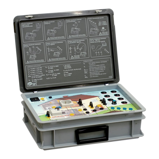
- Page 1 OPERATING MANUAL DEMONSTRATION BOARD DB-1 Revision 1.1 Juli 15, 2009...
-
Page 2: Table Of Contents
TABLE OF CONTENTS Introduction ............................... 3 Safety................................. 4 The front panel – arrangement of sockets and switches................5 Measurements............................7 4.1. Measurement of the short circuit loop impedance................7 4.1.1. Measurement of the short circuit loop impedance in the L-PE circuit..........7 4.1.2. -
Page 3: Introduction
Introduction The DB-1 demonstration board is an indispensable element of training courses regarding realisation of electric measurements. It may be applied in schools, distribution centres of meters used in the power industry as well as in training centres. The board may be used for the purpose of simulation of the following measurements:... -
Page 4: Safety
Safety The DB-1 demonstration board has been designed for the purpose of simulation of measurements, whose results determine the safety conditions of a virtual installation. Therefore, in order to guarantee appropriate operation and correctness of the obtained results, the following recommendations must be followed: Before you proceed to operate the device read thoroughly the present manual and observe the safety regulations and instructions specified by the manufacturer. -
Page 5: The Front Panel - Arrangement Of Sockets And Switches
The front panel – arrangement of sockets and switches. Figure 1. Arrangements of the panel elements of the DB-1 demonstration board. Power supply network socket 230 V Additional PE socket 230 V power supply signalling diode RCD switch Measurement socket... - Page 6 Position of switches simulating irregularities in the electric installation of the measured object. Figure 2. Positions of switches. High earth resistance at P2. R = 1k The acceptable voltage value U has been exceeded during measurements of the RCD parameters in the measurement socket.
-
Page 7: Measurements
Measurements. 4.1. Measurement of the short circuit loop impedance. A reliable and the most commonly used method of protection from electric shock consists in protection from indirect touch in circuits equipped with circuit breakers. The method consists in a automatic disconnection in the case of fault. - Page 8 1) Jumper simulating measurements in the TN network. 2) Jumper placed simulating measurements in the TT network. Figure 3. Network type selection jumpers. Figure 4. Connection of the meter. Expected results: Switch Z „green” for the TN network (TN jumper): = ZL-N of the network + 1,4 L-PE Switch Z...
-
Page 9: Measurement Of The Short Circuit Loop Impedance In The L-N Circuit
4.1.2. Measurement of the short circuit loop impedance in the L-N circuit. Measurements may be performed with any meter for measurements of the short circuit loop whose short circuit current does not exceed 25 A, and whose measurement time does not exceed 60 ms, e.g. MZC-30X, MZC-20X, MPI-5XX. -
Page 10: Realisation Of Measurements Of The Rcd Switch Parameters
∆ where R is the resistance between the earth terminal of the protected device and the earth. 4.2.1. Realisation of measurements of the RCD switch parameters. In order to perform the measurement proceed as follows : - connect the 230 VAC power supply network cable to the socket of the demonstration board, - select the kind of network, TT or TN, using the jumper in the appropriate position (Figure 3), - all the switches simulating irregularities must be in the „green”... -
Page 11: Measurements Of The Earth Resistance
The parameters of the pulse are defined by two values: the duration of the pulse leading edge t and the duration of the semi-peak t The DB-1 demonstration board permits to perform measurements of the earth resistance of three distinct earth electrodes, namely R . Earth resistance measurement R is also possible using the clamp method. -
Page 12: Measurement Of The Earth Electrode Resistance Using Meters Of The Mru Series
4.3.1. Measurement of the earth electrode resistance using meters of the MRU series. 4.3.1.1. Earth resistance measurement R In order to perform the R earth resistance measurement proceed as follows: - disconnect the 230 VAC power supply network cable from the socket of the demonstration board, - remove the TN or TT jumper, the ZW H O jumper, the earth electrode R : ZW R... -
Page 13: Earth Resistance Measurement R
Figure 8. Connection of the meter. Expected results: = 4,7 , R = 200 , R = 200 4.3.1.3. Earth resistance measurement R by means of the technical method. In order to perform the R earth resistance measurement proceed as follows: - disconnect the 230 VAC power supply network cable from the socket of the demonstration board, - remove the TN or TT jumper, the ZW H O jumper, the earth electrode R... -
Page 14: Earth Resistance Measurement R By Means Of The Technical Method Using Current Clamps
4.3.1.4. Earth resistance measurement R by means of the technical method using current clamps. In order to perform the R earth resistance measurement using clamps proceed as follows: - disconnect the 230 VAC power supply network cable from the socket of the demonstration board, - since the measurement of the measurement current is performed with clamps, the user is free to place all the jumpers, - use an auxiliary lead, instead of the jumper on the E2,... -
Page 15: Measurement Of The Earth Resistance Using Meters For Measuring Loop Impedance
Figure 11. Connection of the meter. Expected results: = 11,5 4.3.2. Measurement of the earth resistance using meters for measuring loop impedance. Measurements of the earth resistance may also be performed with meters for measuring the short circuit loop impedance. In order to perform such measurements, the phase conductor of the power supply network is used as an auxiliary source of voltage which permits to generate the measurement current. -
Page 16: Earth Resistance Measurement R
Figure 12. Connection of the meter. Expected results: = 100 of the network 4.3.2.2. Earth resistance measurement R In order to perform the R earth resistance measurement proceed as follows: - connect the 230 VAC power supply network cable to the socket of the demonstration board, - remove the TN or TT jumper, the ZW H O jumper, the earth electrode R : ZW R... -
Page 17: Earth Resistance Measurement R
4.3.2.3. Earth resistance measurement R In order to perform the R earth resistance measurement proceed as follows: - connect the 230 VAC power supply network cable to the socket of the demonstration board, - remove the TN or TT jumper, the ZW H O jumper, the earth electrode R : ZW R jumper,... -
Page 18: Measurements Of The Continuity Of Equipotential Bondings
Figure 15. Connection of the meter. Expected results: Switch in the position 5 m : ρ = 31 m Switch in the position 10 m : ρ = 295 m Switch in the position 20 m : ρ = 5,9 k m 4.5. -
Page 19: Measurement Of The Resistance Of Equipotential Bonding Between P1 And P3
Figure 16. Connection of the meter. Expected results: Switch R in the “green” position: R (P1-P2) = 0,4 cont Switch R in the “red” position: R (P1-P2) = 1 k cont 4.5.2. Measurement of the resistance of equipotential bonding between P1 and P3. In order to perform a measurement of the resistance of equipotential bonding between P1 and P3 proceed as follows: - disconnect the 230 VAC power supply network cable from the socket of the demonstration board,... -
Page 20: Insulation Resistance Measurement
Before the measurements are performed, make sure the measured object is disconnected from the power supply network. This is why the meters manufactured by SONEL S.A. are equipped with a voltmeter. The demonstration board permits a simulation of an insulation resistance measurement. The measurement may be performed in the L-N and L-PE circuits. -
Page 21: Insulation Resistance Measurements In The L-Pe Circuits
4.6.2. Insulation resistance measurements in the L-PE circuits. In order to perform the measurement of the insulation resistance in the L-PE circuit proceed as follows: - disconnect the 230 VAC power supply network cable from the socket of the demonstration board, - place all the switches simulating irregularities in the „green”... -
Page 22: Cleaning And Maintenance
Figure 20. Position of the fuse elements. NOTE: Solely the following fuse elements are approved for the demonstration board: F4A 250V or T3,15 250V. In the case fuse elements which are not specified in the present manual are used, there is a risk of damage to the device and a serious danger for the user. -
Page 23: Technical Data
Auxiliary cable, banana plug – banana plug 0.7m – 1 piece Configuration jumpers – 4 pieces Operating manual Guarantee card 10. Manufacturer The manufacturer of the board providing the guarantee and post-guarantee service is: SONEL S. A. ul. Wokulskiego 11 58-100 Świdnica Poland Fax (0-74) 858 38 08 E-mail: export@sonel.pl Web site: www.sonel.pl...
Need help?
Do you have a question about the DB-1 and is the answer not in the manual?
Questions and answers