
Related Manuals for Samsung QA65Q90RAK


Summary of Contents for Samsung QA65Q90RAK
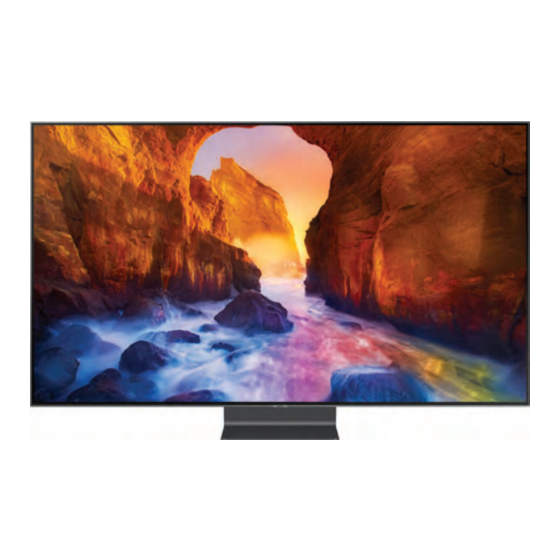
- Page 1 QLED TV Project : QRQ90B Chassis : QWD90 Model : QA65Q90RAK QA75Q90RAK QA82Q90RAK SERVICE Manual QLED TV Contents 1. Precautions 2. Product specifications 3. Disassembly and Reassembly 4. Troubleshooting 5. Wiring Diagram QA82Q90RAK...
-
Page 2: Table Of Contents
2-4. Viewing the Functions ......................2-15 Concept ...................... 2-15 2-4-1. 2019' 2-4-2. Quick Guides ........................2-22 2-4-3. The Samsung Smart Remote ..................2-31 2-4-4. Using the TV Controller ....................2-33 2-4-5. Rear View & One Connect ....................2-34 2-5. Supported subtitles ........................2-35 3. - Page 3 4-4. Audio ............................4-23 4-5. Network ............................4-24 4-6. Smart Hub ..........................4-25 4-7. BlueTooth / WiFi Module ......................4-27 4-8. Replacing Main Board ......................4-28 4-9. Factory Mode ..........................4-32 4-10. Factory Mode Adjustments ....................4-37 4-10-1. Entering Factory Mode ....................4-37 4-10-2. Detail Factory Option ....................4-38 4-10-3.
- Page 4 This Service Manual is a property of Samsung Electronics Co.,Ltd. © 2019 Samsung Electronics Co.,Ltd. Any unauthorized use of Manual can be punished under applicable All rights reserved. International and/or domestic law. Printed in Korea...
- Page 5 Exploded Views and Parts List 1. Exploded View & Part List Exploded View Copyright© 1995-2019 SAMSUNG. All rights reserved.
- Page 6 ASSY SPEAKER P-FRONT; TV-SPK,Q90B,6ohm,10 BN96-48728A ASSY BOARD P-FUNCTION TACT; Y19 Q90 Funct BN59-01314A NETWORK-WLAN CLIENT; WCP730M,78.3x29.3x7. R001A BN96-49062A ASSY COVER P-REAR; 65QRQ90B,PC+ABS+ED20%, BN96-49069A ASSY STAND P-COVER NECK; 65QRQ90B,PP+GF40 BN96-49070A ASSY STAND P-COVER TOP; 65QRQ90B,SS400,CA Copyright© 1995-2019 SAMSUNG. All rights reserved.
- Page 7 Exploded Views and Parts List 2. ONE CONNECT Exploded View & Part List ONE CONNECT Exploded View Copyright© 1995-2019 SAMSUNG. All rights reserved.
- Page 8 Description & Specification Qty. BN96-45940A ASSY COVER P-OC TOP; 65QNQ9FA,PC,V-2,TP00 OC-SMPS BN44-00935B DC VSS-POWER BOARD; P300NQB_NSM,AC/DC,360 BN63-17541A INSULATOR-SMPS; 65QNQ9FA,PC,BLACK,L126.9, BN63-17538A SHIELD-OC TOP; 65QNQ9FA,EGI-SECC,T0.8 BN94-14012E ASSY PCB OC; QRQ85E BN96-48511B ASSY COVER P-OC BOTTOM; 65QRQ90B,PC+ABS+G Copyright© 1995-2019 SAMSUNG. All rights reserved.
- Page 9 BAG PE;HDPE/PE FOAM,T0.015/T0.5,W500,L30 M0131 AA63-01071A GASKET-EMI;EMI Shielding,Conductive Tape M0909 AA63-01387A GASKET-EMI;EMI Shielding,Conductive Tape BN02-00102B TAPE-SINGLE FACE;OPP,T0.15,W25,L50M,WHIT BN39-02437A LEAD CONNECTOR-POWER;QN65Q900R,UL21516,2 OC-SMPSBN44-00935B DC VSS-POWER BOARD;P300NQB_NSM,AC/DC,360 BN62-00883A PAD GAP-THERMAL;QN65Q90RAFXZA,Si,T12.5,L M0131 BN63-02627A GASKET-EMI;Oxford,Conductive Fabric,T8,W BN63-17538A SHIELD-OC TOP;65QNQ9FA,EGI-SECC,T0.8 BN63-17541A INSULATOR-SMPS;65QNQ9FA,PC,BLACK,L126.9, Copyright© 1995-2019 SAMSUNG. All rights reserved.
- Page 10 VARISTOR;24.5V,16VDC,120A,2012,TP,42V,40 ...4 1405-001452 VARISTOR;15V,12VDC,8A,1608,TP,46V,18pF ...4 2007-000137 R-CHIP;2Kohm,5%,1/16W,TP,1005 ...4 2007-000138 R-CHIP;100ohm,5%,1/16W,TP,1005,T0.35 ...4 2007-000143 R-CHIP;4.7Kohm,5%,1/16W,TP,1005,T0.35 ...4 2007-000170 R-CHIP;1Mohm,5%,1/16W,TP,1005,T0.35 ...4 2007-000171 R-CHIP;0ohm,5%,1/16W,TP,1005,T0.35 ...4 2007-000172 R-CHIP;10ohm,5%,1/16W,TP,1005,T0.35 ...4 2007-000173 R-CHIP;22ohm,5%,1/16W,TP,1005,T0.35 ...4 2007-000501 R-CHIP;2.2ohm,1%,1/10W,TP,1608 ...4 2007-000779 R-CHIP;33ohm,1%,1/10W,TP,1608 ...4 2007-001116 R-CHIP;680ohm,1%,1/10W,TP,1608 Copyright© 1995-2019 SAMSUNG. All rights reserved.
- Page 11 2203-006838 C-CER,CHIP;2200nF,10%,6.3V,X5R,TP,1005,T ...4 AD480 2203-006841 C-CER,CHIP;1000nF,10%,16V,X5R,TP,1005,T0 ...4 AD480 2203-006890 C-CER,CHIP;10000nF,20%,6.3V,X5R,TP,1608 ...4 AD480 2203-007271 C-CER,CHIP;2200nF,10%,10V,X5R,TP,1005,T0 ...4 AD480 2203-007544 C-CER,CHIP;100nF,10%,50V,X7R,TP,1005,T0..4 AD480 2203-008315 C-CER,CHIP;22000nF,20%,25V,X5R,TP,2012,T ...4 2703-000158 INDUCTOR-SMD;1uH,10%,0.4Ohm,50mA,45,Mult ...4 2703-000213 INDUCTOR-SMD;470nH,10%,1.35Ohm,35mA,15,M ...4 2703-002269 INDUCTOR-SMD;56nH,5%,1005,T0.5,1.4Ohm,15 ...4 2703-005191 INDUCTOR-SMD;1.5uH,20%,6060,T4.5,0.02Ohm Copyright© 1995-2019 SAMSUNG. All rights reserved.
- Page 12 RESIN PC ABS;235GNH15/6919H,Black,BK0007 BN63-17520A SHIELD-OC BOTTOM;65QNQ9FA,EGI-SECC,T0.5, BN63-17718A SHIELD-OC TOP FRONT;65QNQ9FA,EGI-SECC,T0 RF01 BN67-00327J FOOT-RUBBER;PE400,RUBBER,GRAY,T2.5,, BN91-21269L ASSY SHIELD;QRQ90B 6001-003042 SCREW-MACHINE;FH,+,M3,L10,ZPC(BLK),SWRCH BN39-02309C LEAD CONNECTOR-DIMMING;Q7F,Q7C,Q8C,UL210 BN39-02403D LEAD CONNECTOR-POWER;55LS03,UL21516,26P, BN39-02463A LEAD CONNECTOR-SUB ASSY;QRQ90B,UL21016,1 BN39-02465A LEAD CONNECTOR-SUB ASSY;49, 55 Q70,UL214 Copyright© 1995-2019 SAMSUNG. All rights reserved.
- Page 13 FET-SILICON;PJL9409,P,30V,50A,0.035ohm,3 ...4 1003-003030 IC-LEVEL DRIVER;VLS3RT,QFN,40P,6x6x0.9mm ...4 1103-001564 IC-EEPROM;S-24C512CI-J800,512Kbit,64Kx8, ...4 1105-002989 IC-DDR4 SDRAM;MT53E384M32D2DS-053 WT:E,L ...4 1105-002992 IC-DDR4 SDRAM;MT53E256M32D2DS-053 WT:B,L ...4 1201-004170 IC-AUDIO AMP;TAS880021A,TSSOP,48P,12.5x6 ...4 1203-009063 IC-DC/DC CONVERTER;VPM2SM,QFN,56P,7x7x0..4 1203-009186 IC-POSI.ADJUST REG.;TLV759P01PDRVR,TP,6P ...4 1203-009188 IC-VOL. DETECTOR;G623F11U,TP,8P,4.9x6x1. Copyright© 1995-2019 SAMSUNG. All rights reserved.
- Page 14 R-CHIP;2Kohm,1%,1/16W,TP,1005,T0.35 ...4 2007-007767 R-CHIP;200ohm,1%,1/16W,TP,1005 ...4 2007-007798 R-CHIP;10ohm,1%,1/16W,TP,1005,T0.35 ...4 2007-007992 R-CHIP;1ohm,1%,1/10W,TP,1608 ...4 2007-008294 R-CHIP;33ohm,1%,1/16W,TP,1005,T0.35 ...4 2007-008298 R-CHIP;49.9ohm,1%,1/16W,TP,1005,T0.35 ...4 2007-008596 R-CHIP;0.1ohm,1%,1/4W,TP,3216 ...4 2007-009322 R-CHIP;1.3Kohm,1%,1/16W,TP,1005 ...4 2011-001264 R-NETWORK;10ohm,5%,1/16W,L,CHIP,8P,TP,2..4 2011-001448 R-NETWORK;10ohm,5%,1/16W,L,4P,TP,1.0x1.0 ...4 2011-001519 R-NETWORK;33OHM,5%,1/16W,L,CHIP,4P,TP,1..4 2011-001527 R-NETWORK;4.7Kohm,5%,1/16W,L,CHIP,4P,TP, Copyright© 1995-2019 SAMSUNG. All rights reserved.
- Page 15 2703-004724 INDUCTOR-SMD;8.2uH,20%,5050,T4,0.072Ohm, ...4 2703-005194 INDUCTOR-SMD;3.3uH,20%,6060,T4.5,0.03Ohm ...4 2703-005376 INDUCTOR-SMD;10uH,20%,10.7x10mm,T3.8,0.0 ...4 2703-005715 INDUCTOR-SMD;820nH,20%,11x10mm,T3.8,0.00 ...4 2801-004021 CRYSTAL-SMD;24.576MHz,20ppm,28-AAN,12pF, ...4 2801-005372 CRYSTAL-SMD;24.576MHz,20ppm,HCX-3SB,12 p ...4 3301-001364 BEAD-SMD;1000ohm,1608,TP,1085ohm/108MHz, ...4 3601-001374 FUSE-SURFACE MOUNT;32V,5A,FAST-ACTING,PL ...4 3708-003241 CONNECTOR-FPC/FFC/PIC;96P,0.5mm,SMD-A,AU ...4 3710-004374 CONNECTOR-SOCKET;34P,1R,0.8mm,SMD-A,Au,B ...4 3711-007975 CONNECTOR-HEADER;BOX,10P,1R,1.25mm,SMD-A Copyright© 1995-2019 SAMSUNG. All rights reserved.
- Page 16 GENDER CABLE;DC to RCA Cable,2P,L100,UL2 BN59-01311E REMOCON-SMART CONTROL;2019 TV,SAMSUNG,21 T0527 BN68-00513A LABEL-E PASS;ALL MODEL,WW,YUPO,W50,L15,W BN68-08112A LABEL-SECURITY;ALL,PET,T0.05,W55,L52,GLO BN68-09544F MANUAL USERS;Q90R,XV,VIETNAM,MOJO,0,1 CO BN68-09545B LEAFLET-ACCESSORY KIT;QRQ90B,XY & MR & HC & BN69-13935A BAG ACCESSORY;LDPE,T0.07,W700,L350,TRP,R BN96-49199A ASSY ACCESSORY-FOOT;65QRQ90B,Si,W/W,W/W, Copyright© 1995-2019 SAMSUNG. All rights reserved.
- Page 17 BOX UNIT-IN;65QRQ90B,CB,DW1,C1,L1936,W51 BN95-05486A PRODUCT LCD-SDC;CY-TR065FLLV1V/H,Q90,Bas BN39-02397A LEAD CONNECTOR-DIMMING;Q9F_65,75,UL21016 BN39-02405B LEAD CONNECTOR-POWER;65Q9,UL21516,26P,L7 BN44-00980C DC VSS-DRIVER BOARD;L65S9NRA_RHS,DC/DC,3 BN44-00980D DC VSS-DRIVER BOARD;L65S9NRB_RHS,DC/DC,3 BN97-00031K ASSY MICOM-LD_FW;Y19_S90,19Y_Q90 M0131 BN63-00520A GASKET-EMI;APPOLO_PAL,Conductive Fabric, BN63-17506B COVER-SOURCE PCB LEFT;65QRQ90B,EGI-SECC, BN63-17507B COVER-SOURCE PCB RIGHT;65QRQ90B,EGI-SECC Copyright© 1995-2019 SAMSUNG. All rights reserved.
- Page 18 LED-BIN;SMD(TOP VIEW),BLU,water diff.,12 ..6 1003-002953 IC-LED DRIVER;AS3824A1-ZQFT,QFN,48P,7x7x ..6 2007-000052 R-CHIP;10Kohm,1%,1/10W,TP,1608 ..6 2007-000074 R-CHIP;100ohm,5%,1/10W,TP,1608 ..6 2007-000107 R-CHIP;470Kohm,5%,1/10W,TP,1608 ..6 2007-000946 R-CHIP;47ohm,1%,1/10W,TP,1608 ..6 2007-001723 R-CHIP;15ohm,1%,1/4W,TP,3216 1440 ..6 AD480 2203-000236 C-CER,CHIP;0.1nF,5%,50V,C0G,TP,1608 ..6 AD480 2203-001607 C-CER,CHIP;0.22nF,5%,50V,C0G,TP,1608 ..6 AD480 2203-006698 C-CER,CHIP;1000nF,10%,25V,X7R,TP,1608,T0 Copyright© 1995-2019 SAMSUNG. All rights reserved.
- Page 19 BN60-01459A SPACER-SILICONE;55PMF,Si,L10,WHITE,T1.8, ..5 BN61-15554A FRAME-CHASSIS REAR TOP;65QNQ9FA,PC+GF10% ..6 0103-011284 RESIN PC;LS-3104G/FW9931,White,WT0134,V- BN91-20636B ASSY OPEN CELL-DECORATION;BN63-17656A,Y1 0201-003164 ADHESIVE-UV;190024,CLEAR,UV, Acrylic FD01 BN63-17656A COVER-DECORATION;65QRQ90B,STS430J1L,T0.4 BN96-48138A ASSY OPEN CELL;SDC,65Inch,Y19 New open c ...4 BN81-16264A A/S-ADHESIVE-A.C.F;ADHESIVE-A.C.F,0201-0 ...4 BN81-16789A A/S-ADHESIVE-A.C.F;ADHESIVE-A.C.F,0201-0 Copyright© 1995-2019 SAMSUNG. All rights reserved.
- Page 20 6001-002912 SCREW-MACHINE;CH,+,M3,L3,ZPC(BLK),SWRCH1 BN02-00074F TAPE SINGLE FACE;65QRQ80C,PET,T0.05,W10, BN02-00486A TAPE-DOUBLE FACE;PU FOAM,T0.5,W3.2,L33M, BN02-00595A TAPE SINGLE FACE;65QRQ80C,PET,T0.2,W3,L2 BN60-01539E SPACER-FOAM;PU FOAM,L12.5,BLACK,T0.5,W11 BN60-01612B SPACER-CONDUCTIVE;65QNQ7FC,CONDUCTIVE FA BN63-17419B SHEET-PROTECTION COVER;Q9F,PO,T0.04,W20, BN64-04022A CHASSIS-FRONT BOTTOM;65QNQ9FA,PC+GF10%,V ...4 0103-007368 RESIN PC;LS-3104G,K2495,BK0048,3.0mm V-2 AC155 BN64-04128A CHASSIS-FRONT;65QRQ90B,Al,-,-,NATURAL,Ca Copyright© 1995-2019 SAMSUNG. All rights reserved.
-
Page 21: Product Specifications
2. Product specifications 2. Product Specifications 2-1. Product Information Model QA**Q90RAK Front View * W : Width H : High D : Depth Detail View Color Front : CARBON SILVER / Stand : DARK CARBON SILVER Body 145.01 x 83.12 x 3.99 cm 65"... -
Page 22: Product Specification
Auto Depth Enhancer Contrast Enhancer Auto Motion Plus Film Mode Natural Mode Support Audio Dolby Digital Plus DTS Codec Dialog Enhancement Audio Pre-selection Descriptor Sound Output (RMS) Speaker Type 4.2CH Woofer Multiroom Link Blutooth Audio Smart Service Samsung SMART TV Smart... - Page 23 2. Product specifications Item QA65Q90RAKXXV Smart Service US English, Korean, UK English, French, Bixby German, Italian, Spanish (features vary by language) Voice Interaction VN, IN: Vietnamese Far-Field Voice Interaction Works with Google Assistant Yes (SG only) Works With Alexa TV Plus Web Browser SmartThings App Support SmartThings...
- Page 24 2. Product specifications Item QA65Q90RAKXXV Connectivity Composite In (AV) 1 (Common Use for Component Y) Ethernet (LAN) Audio Out (Mini Jack) Digital Audio Out (Optical) RF In (Terrestrial / Cable input / Satellite input) 1/1(Common Use for Terrestrial)/0 Ex-Link ( RS-232C ) CI Slot HDMI A / Return Ch.
- Page 25 2. Product specifications Item QA65Q90RAKXXV Additional Feature Extended PVR Yes (Auto Game Mode, Game Motion Plus, Game Mode Dynamic Black EQ, Game Enhancer) Freesync FreeSync OSD Language Local Languages Picture-In-Picture BT HID Built-in USB HID Support Teletext (TTX) Time Shift V-Chip IPv6 Support MBR Support...
- Page 26 Audio Pre-selection Descriptor Sound Output (RMS) Speaker Type 4.2CH Woofer Multiroom Link Blutooth Audio Smart Service Samsung SMART TV Smart US English, Korean, UK English, French, Bixby German, Italian, Spanish (features vary by language) Voice Interaction VN, IN: Vietnamese Far-Field Voice Interaction...
- Page 27 2. Product specifications Item QA75Q90RAKXXV Smart Service Works with Google Assistant Yes (SG only) Works With Alexa TV Plus Web Browser SmartThings App Support SmartThings Universal Guide Gallery Convergence TV to Mobile - Mirroring Mobile to TV - Mirroring, DLNA 360 Video Player 360 Camera Support Bluetooth Low Energy...
- Page 28 2. Product specifications Item QA75Q90RAKXXV Connectivity Ex-Link ( RS-232C ) CI Slot HDMI A / Return Ch. Support HDMI Quick Switch Wireless LAN Built-in Anynet+ (HDMI-CEC) Design Design Q - Solid Bezel Type 4 Bezel-less Slim Type Slim Front Color CARBON SILVER Light Effect (Deco) Stand Type...
- Page 29 2. Product specifications Item QA75Q90RAKXXV Additional Feature BT HID Built-in USB HID Support Teletext (TTX) Time Shift V-Chip IPv6 Support MBR Support Ultra Clean View Eco Feature Eco Sensor Energy Efficiency Class Power Power Supply AC100-240V 50/60Hz Power Consumption (Max) 300 W Power Consumption (Stand-by) Power Consumption (Energy Saving Mode)
- Page 30 Audio Pre-selection Descriptor Sound Output (RMS) Speaker Type 4.2CH Woofer Multiroom Link Blutooth Audio Smart Service Samsung SMART TV Smart US English, Korean, UK English, French, Bixby German, Italian, Spanish (features vary by language) Voice Interaction VN, IN: Vietnamese Far-Field Voice Interaction...
- Page 31 2. Product specifications Item QA82Q90RAKXXV Smart Service Works with Google Assistant Yes (SG only) Works With Alexa TV Plus Web Browser SmartThings App Support SmartThings Universal Guide Gallery Convergence TV to Mobile - Mirroring Mobile to TV - Mirroring, DLNA 360 Video Player 360 Camera Support Bluetooth Low Energy...
- Page 32 2. Product specifications Item QA82Q90RAKXXV Connectivity RF In (Terrestrial / Cable input / Satellite input) 1/1(Common Use for Terrestrial)/0 Ex-Link ( RS-232C ) CI Slot HDMI A / Return Ch. Support HDMI Quick Switch Wireless LAN Built-in Anynet+ (HDMI-CEC) Design Design Q - Solid Bezel Type...
- Page 33 2. Product specifications Item QA82Q90RAKXXV Additional Feature OSD Language Local Languages Picture-In-Picture BT HID Built-in USB HID Support Teletext (TTX) Time Shift V-Chip IPv6 Support MBR Support Ultra Clean View Eco Feature Eco Sensor Energy Efficiency Class Power Power Supply AC100-240V 50/60Hz Power Consumption (Max) 435 W...
-
Page 34: Accessories
BN90-10951H(75") BN39-02436B(82") BN91-21171G(82") 3903-001118(65") • HOLDER-CABLE BN61-14021A • Power Cable 3903-001118(75") 3903-001110(82") • Samsung Smart Remote BN59-01311F • Batteries (AAA x 2) 4301-000103 • User Manual BN68-09544F • RUBBER-FOOT BN96-49199A • Warranty Card / Regulatory Guide (Not available in some locations) -
Page 35: Viewing The Functions
Colour Volume 100% by Quantum Dot „ Colours as real as they should be. With Samsung’s unique Quantum Dot technology, QLED cranks the colour volume to a full 100%, giving you realistic colours in dark or bright scene. Quantum HDR 16X „... - Page 36 2. Product specifications Intelligent Mode „ Conditions in your room can change, and your TV needs to adapt. QLED's Intelligent Mode adjusts brightness and volume accordingly. It can even adjust the sound to match the TV content, such as clearing a dialogue in news programs and highlighting a singer’s voice over the background concert.
- Page 37 2. Product specifications Win more games, have more controls „ Lower input lag gaming Don’t let lag hold you back! Using FreeSync(VRR) technology, QLED reduces input lag to give you the real-time gaming speed you need to climb to the top. Embrace QLED speed and get ready for some epic wins. FreeSync technology reduces input lag, with less tearing and stuttering.
- Page 38 Smart Hub & One Remote „ QLED gets even smarter with Smart Hub and Samsung One Remote. They place all the content you want right at your fingertips, from your set-top box to game console, apps, and live TV. All you need is one.
- Page 39 2. Product specifications Ambient Mode „ Even when QLED is turned off, it’s never simply still. Ambient Mode helps QLED mingle with your home décor for a perfectly natural effect. Instead of a simple black screen, you’ll see meaningful images that match your lifestyle, with easy settings and plenty of choices.
- Page 40 „ A truly intelligent home, tailored to your life. With Samsung SmartThings built right in, QLED can connect you with your IoT devices and sensors. You can turn on the lights, check what's in the fridge, and even control the robot vacuum cleaner Samsung SmartThings compatible devices may vary by region.
- Page 41 2. Product specifications Works with „ Life gets easier with expanded compatibility. QLED pairs quickly with a range of smart speakers, including ones made by other brands, like Amazon’s Echo or Google Home, without any extra connectors. Amazon, Alexa, and all related logos are trademarks of Amazon.com, Inc. or its affiliates. Google and related marks and logos are trademarks of Google LLC.
-
Page 42: Quick Guides
Connect the Samsung Smart Remote to your TV to operate the TV. When you turn on the TV for the first time, the Samsung Smart Remote pairs to the TV automatically. If the Samsung When you turn on the TV for the first time, the Samsung Smart Remote pairs to the TV automatically. If the Samsung... - Page 43 2. Product specifications Using Smart Hub „ Connect to Smart Hub for apps, games, movies, and more. Enjoy the multiple functions provided by Smart Hub simultaneously on a single screen. NOTE • The image on your TV may differ from the image above depending on the model and geographical area. When you press the button on your remote control, you can use the following functions and features.
- Page 44 TV is turned off, the TV turns on in Ambient Mode. If you use a remote control other than the Samsung Smart Remote, there may be restrictions to entering Ambient mode. Because this function is a QLED TV-specific function, it may not be supported depending on the model.
- Page 45 If you press the button when the TV is turned off, the TV turns on in Ambient Mode. If you use a remote control other than the Samsung Smart Remote, there may be restrictions to entering Ambient Mode. Ambient Mode browser screen NOTE •...
- Page 46 This function may not be supported depending on the geographical area. • Photo Allows you to set a photo stored in your mobile device or Samsung Cloud as the wallpaper of the Ambient Mode screen. To import photos from your mobile device or Samsung Cloud, use the SmartThings app on your mobile device.
- Page 47 2. Product specifications Shortcuts „ You can easily use the contents of Sources without running a series of commands. To display the Shortcuts menu screen, press and hold the button for 1 second or more. To return to the TV mode, press the button.
- Page 48 £ Talking with Bixby using buttons You can also make a conversation with Bixby using the Samsung Smart Remote buttons. Press and hold the button on your Samsung Smart Remote, say a command, and then release the button. The TV recognises the voice command.
- Page 49 ID. Sign in to your account with your voice, that is, your registered voice ID. If you are signed out of your Samsung account, select My Profile to sign in.
- Page 50 2. Product specifications All Services You can learn the voice commands that let you use Bixby in various situations. Use the directional buttons to move to the desired command, and then press the Select button. You can operate the TV with various voice commands. View Tutorial The popup window on using Bixby appears.
-
Page 51: The Samsung Smart Remote
The images, buttons, and functions of the Samsung Smart Remote may differ depending on the model. • The Universal Remote function operates normally only when you use the Samsung Smart Remote that comes with The images, buttons, and functions of the Samsung Smart Remote may differ depending on the model. - Page 52 Installing batteries into the Samsung Smart Remote Press the button at the top rear of the Samsung Smart Remote. The body will pop out slightly from the body cover. 1. Press the button at the top rear of the Samsung Smart Remote. The body will pop out slightly from the Turn the remote over, and then slide the body of the remote upwards until the battery compartment is revealed.
-
Page 53: Using The Tv Controller
The screen may dim if the protective film on the SAMSUNG logo or the bottom of the TV is not detached. The screen may dim if the protective film on the SAMSUNG logo or the bottom of the TV is not detached. Please •... -
Page 54: Rear View & One Connect
2. Product specifications 2-4-5. Rear View & One Connect The TV turns off when the One Invisible Connection cable is disconnected, and turns on when it is connected. 2-34... -
Page 55: Supported Subtitles
2. Product specifications 2-5. Supported subtitles Subtitle formats „ Name Format MPEG-4 Timed text .ttxt SAMI .smi SubRip .srt SubViewer .sub Micro DVD .sub or .txt SubStation Alpha .ssa Advanced SubStation Alpha .ass SMPTE-TT Text .xml Video formats with subtitles „... - Page 56 2. Product specifications Supported music formats and codecs „ File extension Format Codec Note *.mp3 MPEG MPEG1 Audio Layer 3 *.m4a *.mpa MPEG4 *.aac *.flac FLAC FLAC Supports up to 2 channels *.ogg Vorbis Supports up to 2 channels WMA is supported up to 10 Pro 5.1 channels. *.wma WMA lossless audio is not supported.
-
Page 57: Disassembly And Reassemble
This section of the service manual describes the disassembly and reassembly procedures for the LED TV. Disconnect the LED TV from the power source before disassembly. Follow these directions carefully. Use the Samsung Open Jig and Cushion to remove the Rear Cover. • Open Jig Tool, Protection Cushion (curved models Only) - Page 58 3. Disassembly and Reassemble Description & Screws Picture Description Place the TV face down onto a protective surface and remove the 4 screws on the upper stand mount from the TV. ASSY ACCESSORY-SCREW 6003-001907 SCREW-TAPTYPE : M4 x L14, ZPC(BLK) •...
- Page 59 3. Disassembly and Reassemble Description & Screws Picture Description • 65 inches : 12 point Locking Center : 3 Point Locking Bottom : 8 point Locking • 75 inches : 14 point Locking Center : 2 Point Locking Bottom : 8 point Locking •...
- Page 60 3. Disassembly and Reassemble Description & Screws Picture Description Remove the ASSY COVER P-REAR. • 65 inches • 75 inches • 82 inches Remove the ASSY SPEAKER P-FRONT. ASSY SPEAKER P-FRONT Cable • ASSY SPEAKER P-FRONT Cable • : Assy SPK to Panel Hole 4 Points ASSY SPEAKER P-FRONT...
- Page 61 3. Disassembly and Reassemble Description & Screws Picture Description Remove the NETWORK-WLAN CLIENT. LEAD CONNECTOR-SUB ASSY • LEAD CONNECTOR-SUB ASSY <Disassemble WiFI> NETWORK-WLAN CLIENT Remove the ASSY BOARD P-FUNCTION TACT. ASSY BOARD P-FUNCTION TACT Cable • ASSY BOARD P-FUNCTION TACT Cable Screws 6001-003042 SCREW-MACHINE : M3 x L10, ZPC(BLK)
- Page 62 3. Disassembly and Reassemble Description & Screws Picture Description Remove cables from TV MAIN, LD/SMPS (A/B) Board. • LEAD CONNECTOR-DIMMING (Main - LD/SMPS B) • LEAD CONNECTOR-POWER (Main - LD/SMPS A) • FFC Cables Remove the ASSY PCB MAIN BOARD. •...
- Page 63 3. Disassembly and Reassemble Description & Screws Picture Description Remove the power and OC (One Connect) LD/SMPS B cables connected to the TV panel, then use the discharge tool to discharge power from each board. 65" : Measurement point <Discharging> Measurement point LD/SMPS A •...
- Page 64 3. Disassembly and Reassemble Description & Screws Picture Description • 82" : Measurement point LD/SMPS A <Discharging> LD/SMPS B Remove cables from LD/SMPS (A/B) Board. • LEAD CONNECTOR-POWER LD/SMPS A (LD/SMPS A - LD/SMPS B) • LEAD CONNECTOR-DIMMING (LD/SMPS A - LD/SMPS B) •...
- Page 65 3. Disassembly and Reassemble Description & Screws Picture Description • LD/SMPS B : 82" LD/SMPS B 2 Slide to the Left to release the board Locking Fixing Hole Locking Fixing Hole Gently lift the Left edge to unlock the Fixing Hole LD/SMPS A board locking/ Fixing Hole).
- Page 66 3. Disassembly and Reassemble Description & Screws Picture Description Completed the disassembly. NOTE Reassembly procedures are in the reverse order of disassembly procedures. 3-10...
-
Page 67: One Connect Disassembly
3. Disassembly and Reassemble 3-2. One Connect Disassembly Description & Screws Picture Description Remove the 3 screws from ASSY COVER P-OC BOTTOM. Screws 6003-000282 SCREW-TAPTYPE : M3 x L8, ZPC(BLK) • C/BOTTOM+C/TOP Use the Open Tool to unlock each corner. Open Jigs •... - Page 68 3. Disassembly and Reassemble Description & Screws Picture Description Remove the Cables. • One Connect power supply power cable. CNW803 (20 Pin) LEAD CONNECTOR-POWER Remove the 5 screws at each marked screw location on the board. Screws 6003-000283 SCREW-TAPTYPE : M3 x L8, ZPC(WHT) •...
- Page 69 3. Disassembly and Reassemble Description & Screws Picture Description Remove the 4 screws on the One Connect Board. Screws 6003-000283 SCREW-TAPTYPE : M3 x L8, ZPC(WHT) • MAIN BOARD+C/BOTTOM Completed the disassembly. NOTE Reassembly procedures are in the reverse order of disassembly procedures. 3-13...
-
Page 70: Troubleshooting
4. Troubleshooting 4. Troubleshooting 4-1. Function Control Operation Test <To CN1501 Main Board> <Standby LED Status> <5 Function Switch> CN1501 (FUNCTION & IR) IR_GND A3.3V_PW SENSOR_SCL_I2C SENSOR_SDA_I2C KEY_INPUT1 KEY_INPUT2 LED_STB_OUT IR_OUT_1 IR_OUT_2 FUNCTION/IR Control Test „ Place TV in Power Standby : Check Status. -
Page 71: Power
4. Troubleshooting 4-2. Power 4-2-1. TV POWER STANDBY • 65 inches : LD/SMPS A CN9003A CNM803B CNM803A Main Connector (POWER) • 75 inches : LD/SMPS A CN9003A CNM803B CNM803A Main Connector (POWER) - Page 72 4. Troubleshooting • 82 inches : LD/SMPS A CN9003A CNM803B CNM803A Main Connector (POWER) CNM803A (MAIN Connector) B-GND B-GND B350V B350V VAMP B13V VAMP B13V VAMP B13V A13V PS_ON 20 POWER_LOW Fault 5.5V CN9003A (LD/SMPS A Connector) SEAMLESS SCL_LED BLU_ON/OFF TEST_SD SDA_LED TEST_LD...
- Page 73 4. Troubleshooting TV in Standby Check Standby LED Indicator If Not Lit: Check One Connect Box is Powered. • If OK Check OCB Cable to TV (Miss Connections or damaged cable) • If OK Check A13V CNM803A Pin 17 on TV LD/ SMPS A •...
-
Page 74: Tv Power On Sequence
4. Troubleshooting 4-2-2. TV POWER ON SEQUENCE • 65 inches : LD/SMPS A FUSE CNM803A Main Connector (POWER) VAMP / B13V 35Vdc LED Supply CNM803A (MAIN Connector) B-GND B-GND B350V B350V VAMP B13V VAMP B13V VAMP B13V A13V PS_ON 20 POWER_LOW Fault 5.5V Power On... - Page 75 4. Troubleshooting • 75 inches : LD/SMPS A FUSE CNM803A Main Connector (POWER) VAMP / B13V 35Vdc LED Supply CNM803A (MAIN Connector) B-GND B-GND B350V B350V VAMP B13V VAMP B13V VAMP B13V A13V PS_ON 20 POWER_LOW Fault 5.5V Power On •...
- Page 76 4. Troubleshooting • 82 inches : LD/SMPS A FUSE CNM803A Main Connector (POWER) CNM803A (MAIN Connector) B-GND B-GND B350V B350V VAMP B13V VAMP B13V VAMP B13V A13V PS_ON 20 POWER_LOW Fault 5.5V Power On • 82 inches : LD/SMPS B CN9003B LD/SMPS A Connector CN9003B (LD/SMPS A Connector)
- Page 77 4. Troubleshooting Power TV On Check A13V pin 17 (Supplied by One Connect Box) • If missing check One Connect Operation & Cables to the TV Check PS_ON pin 19 0.2Vdc (when off) changes to 3.3Vdc (on) NOTE • Will stay On for short time when powered off. If PS_ON Error (won’t change or missing voltages) Check &...
-
Page 78: One Connect Power On Sequence
4. Troubleshooting 4-2-3. One Connect POWER ON SEQUENCE • 65 / 75 / 82 inches : One Connect SMPS CNM803 CNM803 (POWER) IR_SMPS FAIL COUNT PS_ON POWER_LOW A13V A13V A13V A13V B350V B350V B_GND B_GND Power On Connect OCB to TV & Place in Power Standby Check A13V for 12.8Vdc on pins... -
Page 79: Ocb Self Power Supply
4. Troubleshooting 4-2-4. OCB Self Power Supply • 65 / 75 / 82 inches : One Connect SMPS CNM803 CNM803 (POWER) IR_SMPS FAIL COUNT PS_ON POWER_LOW A13V A13V A13V A13V B350V B350V B_GND B_GND Remove AC Power to the OCB & Remove Cover (follow Disassembly Procedure). Connect Discharge Tool across leads of each large Capacitors to remove its charge. - Page 80 4. Troubleshooting IF TEST CABLE IS NOT AVAILABLE „ • Perform steps 1 through 3. Check A13V for 12.8Vdc at board locations Labeled A11.8V and GND (See the picture below.) 13Vdc Check B350 for approx 360Vdc at board test wire locations Labeled B332V and BGND (See the picture below.) 350Vdc 350Vdc GND 4-11...
-
Page 81: Backlight Dimming Control & Bl Supply Path
4. Troubleshooting 4-2-5. BACKLIGHT Dimming Control & BL Supply Path • Over 400 Sections of BACKLIGHT Control • 65 / 75 inches LD/SMPS B <Example with panel ribbons removed from> LD/SMPS A LED Panel Connectors LD/SMPS A 35Vdc LED Supply CN9003A CNM803B CNM803A... - Page 82 4. Troubleshooting • 82 inches LD/SMPS B LD/SMPS A <Example with panel ribbons removed from> LD/SMPS B LD/SMPS A LED Panel Connectors LED Panel Connectors CNM803A LD/SMPS A CN9003A CN9003B CN9003A CNM803B LD/SMPS B CNM803A LED Panel Connectors Dimming BL Control CN1102_SPI (DIMMING) PWM_DIMMING_OUT12_SDATA 4 LED Panel Connectors...
-
Page 83: Backlight
4. Troubleshooting 4-2-6. BACKLIGHT • 65 / 75 inches : LD/SMPS A/B LD/SMPS B LD/SMPS A 35Vdc LED Supply VAMP / B13V 35Vdc LED Supply CN9003B CNM803A LD/SMPS A Connector MAIN Connector 35Vdc (65") CN9003B (LD/SMPS A Connector) CONTACT SERIAL_DATA 4 SERIAL_STT SERIAL_UHR TEST_LD... - Page 84 4. Troubleshooting If TV Powers On but BACKLIGHTS OFF Check BLU_ON 0V (when Off) to 3.6Vdc (on) at CN9003B pin 11 • If no change replace TV Main Board or OC Box • If BLU_ON is OK Check B350Vdc Pins 5 , 6 with B-GND REF Pins CNM803A •...
-
Page 85: Backlight Quick Test
4. Troubleshooting 4-2-7. Backlight Quick Test • One Connect Power Supply to TV SMPS CNM803 CNM803A ONE CONNECT BOX LD/SMPS A CNM803 (POWER) FAIL_COUNT IR_SMPS POWER_LOW PS_ON Backlight Test Cable A13V A13V A13V CNM803 CNM803 A13V A13V B350V B350V B350V B_GND B_GND ONE CONNECT BOX... - Page 86 4. Troubleshooting TV LD/SMPS A & LD/SMPS B „ Remove TV Back Cover (Follow Repair Preparation Procedure). Connect Discharge Tool across leads of each large Capacitors to remove its charge. Discharge Tool Remove Connector CNM803A on LD/SMPS A Board. Remove CN9003A on LD/SMPS B Board (Backlight Control).
-
Page 87: Video
4. Troubleshooting 4-3. Video 4-3-1. ONE CONNECT Main Section „ Cable Video Operation • If No Video Check connection status of One Connect Cable Reconnect One Connect Cable both side (TV and OCL) • If NG: Replace One Connect Box / Cable (defective) TV MAIN (defective) 4-18... -
Page 88: Main/T-Con Board
4. Troubleshooting 4-3-2. MAIN/T-CON BOARD • Scaller & US Post of MUSE-M Main CPU Section £ PRE FRC Main Section £ POST FRC Main Section £ T-CON Section Scaller & US Post of MUSE-M Main CPU Section „ Customer Picture Test 1 Mute >... - Page 89 4. Troubleshooting POST FRC Main Section „ POST FRC (Factory Mode) Video Operation Generated at Post FRC in TV Main Board • If OK: Check/Replace defective TV Main Board • If Noisy: Mute £ 3 £ 6 £ 9 £ Mute T-CON Section „...
-
Page 90: Panel
4. Troubleshooting 4-3-3. PANEL If Noisy Video: Soc T-CON Pattern in Factory Mode • Use type of Noise observed (Bars, single lines, video distortion, etc to help.) • If noise is only on one half of screen check / swap panel cables. •... -
Page 91: Check Test Patterns
4. Troubleshooting 4-3-4. Check Test Patterns • ENTER : Factory mode Test Pattern £ £ Main Board Muse-M Scaler Pattern / US Post Pattern FRC Pre Test Pattern FRC Post Test Pattern T-CON SoC TCON Test Pattern [Factory Mode] Verify " Scaler Pattern"... -
Page 92: Audio
4. Troubleshooting 4-4. Audio • £ £ Source (One Connect) One Connect/TV Main Board Speakers Source (One Connect) „ • No TV Sound Menu £ Audio £ Speaker Settings set to TV Speaker • Noisy / Distorted TV Audio Customer Menu £... -
Page 93: Network
4. Troubleshooting 4-5. Network <TV> <Router> <Internet> TV to Router " Failure" „ Check Network Status Check Network Status (TV Router Internet) Wired & Wireless MAC Address in Customer Support Menu. • No Wired MAC Address : Replace Main Board. •... -
Page 94: Smart Hub
Samsung Apps „ • If it Fails: Reset Smart Hub. Samsung Apps load correctly. Perform " Apps Reset" in Factory Mode. Go to Smart Hub and complete Terms of Agreement and set up information. Samsung Apps load correctly. Before selecting an App, allow Apps to load or failure wilre-occur. - Page 95 4. Troubleshooting For Netflix Operation/Connection Issues: Check Certificate & Netflix ESN Status in Factory Mode. • If Certificate and ESN exists, " CO", "NfO", change the 8.8.8.8 • If Certificate is missing, " C/" replace the TV’s Main Board. • If ESN number is missing: NF/ do not replace the Main Board. Reset TV Clock and check for correct Time & Date. Netflix relies on correct settings. Reset Smart Hub. / Reset Apps In Factory Mode. For Streaming Issues: •...
-
Page 96: Bluetooth / Wifi Module
5 Vdc 5 Vdc WIFI_WOW 3.3 Vdc 3.3 Vdc BTWIFI_NRESET 3.3 Vdc 3.3 Vdc Contact Samsung < - Wired MAC Address : xx:xx:xx:xx:xx:xx Missing or Error : Replace Main Board. - Wireless MAC Address : xx:xx:xx:xx:xx:xx - Bluetooth Address : xx:xx:xx:xx:xx:xx... -
Page 97: Replacing Main Board
4. Troubleshooting 4-8. Replacing Main Board When replacing Main Board, certain values needs to be manually input in Factory menu to complete the replacement. Steps to Replace Main Board „ Enter Factory Menu (Use Factory Remote only). • Power TV on : Select TV Source Info/Factory Option... - Page 98 4. Troubleshooting Writing Type • For Quick Entry of Type. Confirm Type from Option Byte Table for your TV. Home Updates Exit Select Writing Type. Factory Reset " Set Panel Type" appears. Type 82A1QU9TR Enter exact Model Type using cursors. Writing Type Select Local Set...
- Page 99 4. Troubleshooting SW Model • Check Label Rating of the TV(located on the Rear Cover). SW Model is digits after "/" in Version No. Choose same SW Model code from the list. Home Updates Exit Factory Reset Type 82A1QU9TR Writing Type Local Set ED_VIET SW Model...
- Page 100 4. Troubleshooting Model Code • For Quick Entry of Model Code. Confirm Model Code from Option Byte Table for your TV. Home Updates Exit Select Model Code. Factory Reset " Set Model Code" appears. Type 82A1QU9TR Enter exact Model Code using cursors. Writing Type If you entered over 19 digits an Information...
-
Page 101: Factory Mode
4-9. Factory Mode Setting TV into Factory Mode „ Factory Remote Power TV ON. Select TV Source. Info → Factory. MENU for return. AA81-00243A Samsung IR Remote TV Power Standby. Press as follows. • Remote Button NTSC MUTE POWER INFO MENU MUTE... - Page 102 4. Troubleshooting Performing Factory Reset Enter Factory Mode. Select Option £ Factory Reset TV will power off. Perform ALL TV Settings. (New out of box condition) First Screen Appearing in Factory Mode • Sample : Testing Items Micom Version Sub Micom Tizen Platform info BT Version E-Manual Blaster Version...
- Page 103 4. Troubleshooting £ Test Patterns „ Main Board Muse-M Scaler Pattern / US Post Pattern FRC Pre Test Pattern FRC Post Test Pattern T-CON SoC TCON Test Pattern [Factory Mode] Verify " Scaler Pattern" and "US Post Pattern". Scaler Pattern Verify "...
- Page 104 4. Troubleshooting £ Info £ ER Count „ • WD Count : Watch Dog (Hardware related issue). • AR Count : Auto Reset (software (i.e. Apps) related. important Error Count Status Screen. • Verify each item listed. 4-35...
- Page 105 4. Troubleshooting Factory Mode £ Control £ EDID „ Remove ALL HDMI connections. Factory Mode → Control → EDID. (→ Enter Key) Option EDID Control Sub Option Debug Hotel Option Shop Option ADC/WB Asia Option Advanced Sound Select EDID/OFF to ON. (→ Right Arrow Key) EDID ON/OFF Select EDID WRITE ALL. (→ Enter Key) EDID WRITE ALL Success Wait to Success. (→...
-
Page 106: Factory Mode Adjustments
4. Troubleshooting 4-10. Factory Mode Adjustments 4-10-1. Entering Factory Mode To enter [ Service Mode] press the remote-control keys in this sequence : With Consumer Remote (IR Remote) Remote Button : NTSC POWER OFF MUTE POWER ON POWER OFF INFO MENU MUTE POWER ON... -
Page 107: Detail Factory Option
4. Troubleshooting 4-10-2. Detail Factory Option NOTE If you replace the main board with new one, please change the factory option as well. The options you must change are "Type". QA65Q90RAKXXV „ • PANEL / LD/SMPS / MAIN / Assy One Connetor Information Side Version AA04 PANEL... - Page 108 4. Troubleshooting QA75Q90RAKXXV „ • PANEL / LD/SMPS / MAIN / Assy One Connetor Information Side Version FA01 PANEL LD/SMPS Vendor Vendor HANSOE Vendor HANSOE Code Spec Type Code Spec Code Spec BN95-05484A CY-TR075FLLV1V/H 75A1QU9TR BN44-00980E L75S9NRA_RHS BN44-00980F L75S9NRB_RHS MAIN Assy One Connetor ASSY CHASSIS ASSY PCB MAIN...
- Page 109 4. Troubleshooting QA82Q90RAKXXV „ • PANEL / LD/SMPS / MAIN / Assy One Connetor Information Side Version FA01 PANEL LD/SMPS Vendor Vendor HANSOE Vendor HANSOE Code Spec Type Code Spec Code Spec BN95-05483A CY-TR082FLLV1V/H 82A1QU9TR BN44-00981A L82S9NA_RHS BN44-00981B L82S9NB_RHS MAIN Assy One Connetor ASSY CHASSIS ASSY PCB MAIN...
-
Page 110: Factory Data
4. Troubleshooting 4-10-3. Factory Data Option „ Factory Menu Name Data Range Factory Reset Type 65" 65L1QU9TR AA04 75" 75A1QU9TR FA01 82" 82A1QU9TR FA01 Writing Type Local set ED_VIET SW Model QRQ90 Model Code QA82Q90RAKXXV 65/75/82 TUNER PAL,DVB-T2/C Ch Table NONE MRT Option Engineer Option... - Page 111 4. Troubleshooting Factory Menu Name Data Range TTX Group UserOSD OPTION_SWU LMF LEAVE THRESHOLD LMF TRIM THRESHOLD LMF TERM THRESHOLD FAnet Thread CI CPLD Version ACM_MC UNIQUE TRIPLET T-CON Device KANT-M2 SPI Protection FKP Server Type Default Preloading Support Multitasking Support Browser preloading Support FULL EXT IR Boot Support...
- Page 112 4. Troubleshooting Factory Menu Name Data Range Shopmode Picture Reset Game Motion Demo Asia Option Mono Last Memory SOUND • High Devi If the broadcast signal is not good, TV will complement the characteristics of the signal (most use when weak signal comes from the growing area countries) •...
- Page 113 4. Troubleshooting Debug „ Factory Menu Name Data Range Spread Spectrum MAIN DDR SSC ON OFF MAIN DDR SSC Value MAIN Vx1 SSC ON/OFF MAIN Vx1 SSC Value TCON-B DDR SSC ON/OFF TCON-B DDR SSC Period TCON-B DDR SSC Modulation MAIN USIT SSC ON/OFF BYPASS MAIN USIT SSC MF...
- Page 114 4. Troubleshooting Factory Menu Name Data Range Panel S/N 3 [Invalid UTF-8] Panel S/N 4 [Invalid UTF-8] MPEG Margin H.264 Margin Voice Debug Power Management Cert Option Waiting RM_BIST_DTV RM_BIST_ATV RM_BIST_CABLE Stress Mode Log Analyzer Error Popup On/Off DeadLock KILL CES Option CES Convergence Option CES ATSC 3_0...
- Page 115 4. Troubleshooting „ Factory Menu Name Data Range • Self Test(for HW) the Output of test pattern from each IC Info Reset Apps Reset SVC Reset SPI Flash Reset Data Sync Reset Factory Data Reset OPTION_HDMI HOT PLUG DURATION 600ms HDMI FLT CNT SIG HDMI FLT CNT LOS HDMI MUTE TIME...
- Page 116 4. Troubleshooting Factory Menu Name Data Range SOC TCON2 Pattern Level SOC TCON3 Pattern SOC TCON3 Pattern Level Upgrade T-CON DATA UPGRADE T-CON FW UPGRADE T-CON CheckSum T-CON2 DATA UPGRADE T-CON2 FW UPGRADE T-CON2 CheckSum PANEL EEPROM UPGRADE PANEL FLASH UPGRADE Logic Usb D/L •...
- Page 117 4. Troubleshooting Factory Menu Name Data Range ATV IF AGC SPEED Upgrade UHD OSD Test Main USB Path JackP USB Path Apps Update Picture Direct Source Banner Hide Auto Detection Group V APP KantS Cutoff PEQ Restart No SVC Panel ORIGINAL Serial number Writing S/N ADC/WB „...
- Page 118 4. Troubleshooting Factory Menu Name Data Range White Balance R-Offset G-Offset B-Offset R-Gain G-Gain B-Gain WB-W2_R_Offset WB_W2_B_Offset WB_W2_R_Gain WB_W2_B_Gain WB_N_R_Offset WB_N_B_Offset WB_N_R_Gain WB_N_B_Gain MGA On/Off R1_Gain G1_Gain B1_Gain R2_Gain G2_Gain B2_Gain R3_Gain G3_Gain B3_Gain R4_Gain G4_Gain B4_Gain R5_Gain G5_Gain B5_Gain R6_Gain G6_Gain B6_Gain R7_Gain...
- Page 119 4. Troubleshooting Factory Menu Name Data Range R8_Gain G8_Gain B8_Gain R9_Gain G9_Gain B9_Gain R10_Gain G10_Gain B10_Gain SPI White Balance SPI White Balance On/Off SPI R-Offset SPI G-Offset SPI B-Offset SPI R-Gain SPI G-Gain SPI B-Gain SPI N Rgain SPI N Bgain SPI N Roffset SPI N Boffset SPI W2 Rgain SPI W2 Bgain SPI W2 Roffset SPI W2 Boffset...
-
Page 120: Rs-232C
4. Troubleshooting 4-11. RS-232C • RS232C Control Port : COM#(Serial) Bit rate : 115200 Data Bit : 8 bit Parity : None Stop Bits : 1 Flow Control : None • Description of RS232C Pin# Name Full Name Pin# Name Full Name Pin# Name Full Name... -
Page 121: Av Control Tabe
4. Troubleshooting 4-12. AV Control Tabe Control Item Cmd1 Cmd2 Cmd3 Value General Power Power 0x00 0x00 0x00 0x00 0x01 0x02 Volume Direct 0x01 0x00 0x00 (0~100) 0x01 0x00 Down 0x02 0x00 Mute 0x02 0x00 0x00 0x00 Direct 0x04 Continuous 0x03 0x00 0x01... - Page 122 4. Troubleshooting Control Item Cmd1 Cmd2 Cmd3 Value PICTURE BackLight(CellLight) 0~20 0x01 0x00 (0~20) Contrast 0~100 0x02 0x00 (0~100) Brightness 0~100 0x03 0x00 (0~100) Sharpness 0~100 0x04 0x00 (0~100) Color 0~10 0x05 0x00 (0~100) Tint 0x06 0x00 (0~100) Advanced Settings Black Tone 0x07 0x00...
- Page 123 4. Troubleshooting Control Item Cmd1 Cmd2 Cmd3 Value PICTURE Advanced Settings Color Space Custom Cyan 0x04 Color Magenta 0x05 Color Space Custom 0~100 0x13 0~100 Color Red Value Color Space Custom 0~100 0x14 0~100 Color Green Value Color Space Custom 0~100 0x15 0~100...
- Page 124 4. Troubleshooting Control Item Cmd1 Cmd2 Cmd3 Value PICTURE Film Mode Auto2 0x02 Cinema Smooth 0x03 Auto Motion Plus 0x06 0x00 Clear 0x01 Standard 0x02 Smooth 0x03 Custom 0x04 Blur Reduction 0x0b 0x01 value Judder Reduction 0x02 value LED Clear Motion 0x03 0x00 LED Clear Motion...
- Page 125 4. Troubleshooting Control Item Cmd1 Cmd2 Cmd3 Value PICTURE Screen Adjustment Position Position3 0x02 Position4 0x03 Reset Picture Reset Picture 0x0d 0x0b 0x00 0x00 3D Mode 0x0e 0x0c 0x00 0x00 2D->3D 0x01 Side By Side 0x02 Top Bottom 0x03 Line By Line 0x04 Vertical Line 0x05...
- Page 126 4. Troubleshooting Control Item Cmd1 Cmd2 Cmd3 Value PICTURE Sound_Select_ 0x01 Channel_Up 0x05 0x00 Channel_Down 0x01 Sound Sound Mode Standard 0x0c 0x00 0x00 0x00 Music 0x01 Movie 0x02 Clear Voice 0x03 Amplify 0x04 Equalizer Balance 0x01 0x00 (0~20) 100hz 0x01 (0~20) 300hz 0x02...
- Page 127 4. Troubleshooting Control Item Cmd1 Cmd2 Cmd3 Value Sound TV Installation Type Stand 0x0c 0x00 0x00 Wallmount 0x01 Audio Delay Dealy Value (0~250) 0~250 0x0d 0x00 (0x00~0xFA) Key Generation *Refer for 0x0d 0x00 0x00 Table Show/Hide Control Show 0x0e 0x00 0x00 0x00 Hide...
-
Page 128: Updating The Tv's Software
TV to update. To update using a USB device, download the update package from Samsung.com to your computer. Then, save the update package in the USB device's top-level folder. Otherwise, the TV will not be able to locate the update package. -
Page 129: Wiring Diagram
5. Wiring Diagram 5. Wiring Diagram 5-1. Wiring Diagram • 65 / 75 inches_Wiring Diagram LD/SMPS B CN9003A CNM803B CNM803A CNM803A CN9003B LD/SMPS A CN9003A CN1102_SPI CN1403 CN201 TV Board ACN01 CN200 CN1300 CN1301_UT CN1501 SPEAKER R SPEAKER L LOGO BT/WIFI Func on ONE CONNECT... - Page 130 5. Wiring Diagram • 75 inches_inner...
- Page 131 5. Wiring Diagram Cables „ NOTE • The image may differ with the specific model and area. • The code number can be changed, see "Exploded Views" provided on the site. • 65 / 75 inches LD/SMPS B CN9003A CNM803B CNM803A CNM803A CN9003B LD/SMPS A CN9003A CN1102_SPI CN1403 CN201 TV Board ACN01 CN200 CN1300 CN1301_UT CN1501 SPEAKER R SPEAKER L LOGO BT/WIFI Func on...
- Page 132 5. Wiring Diagram Part Name & Connection Part Spec Code No. 10P/L125 65" BN39-02463A LEAD CONNECTOR-SUB ASSY Main - FUNCTION 10P/L150 75" BN39-02463B 16P/L800 65" BN39-02397A LEAD CONNECTOR-DIMMING LD/SMPS A - LD/SMPS B 16P/L900 75" BN39-02397B 26P/L750 65" BN39-02405B LEAD CONNECTOR-POWER LD/SMPS A - LD/SMPS B 26P/L850 75"...
- Page 133 5. Wiring Diagram • 82 inches_Wiring Diagram CN9003 CN9002 CN9001 CNM803A CN9003A CN9005 CN9004 LD/SMPS B LD/SMPS A CN9004 CN9005 CN9003A CNM803A CN9001 CN9002 CN9003 CN1102_SPI CN201 CN1403 TV Board ACN01 CN200 CN1300 CN1301_UT CN1501 SPEAKER R SPEAKER L LOGO BT/WIFI Func on ONE CONNECT...
- Page 134 5. Wiring Diagram Cables „ • 82 inches CN9003 CN9002 CN9001 CNM803A CN9003A CN9005 CN9004 LD/SMPS B LD/SMPS A CN9003A CN9004 CN9005 CNM803A CN9001 CN9002 CN9003 CN1102_SPI CN201 CN1403 TV Board ACN01 CN200 CN1300 CN1301_UT CN1501 SPEAKER R SPEAKER L LOGO BT/WIFI Func on...
- Page 135 5. Wiring Diagram Part Name & Connection Part Spec Code No. LEAD CONNECTOR-SUB ASSY 10P/190mm 82" AH39-01232D Main - FUNCTION LEAD CONNECTOR-POWER 26P/L750 82" BN39-02405D LD/SMPS A - LD/SMPS B LEAD CONNECTOR-ETC 16P/L1200 82" BN39-02332B LD/SMPS A - LD/SMPS B LEAD CONNECTOR-POWER 26P/L125 82"...
-
Page 136: Connector
5. Wiring Diagram 5-2. Connector 5-2-1. Main Board • 65 / 75 / 82 inches CN201 CN1102_SPI (POWER) (DIMMING) CN1403 (BT/WIFI) CN200 (OC CONNECTOR) ACN01 (AMP) CN1300 CN1501 CN1301_UT (USI-T LEFT) (FUNCTION & IR) (USI-T RIGHT) Main Board Pin Map „... - Page 137 5. Wiring Diagram CN200 (OC CONNECTOR) CN1102_SPI (DIMMING) SERDES_RX_L1- PWM_DIMMING_ SERDES_RX_L1+ OUT12_SDATA SERDES_TX_L1+ SERDES_TX_L1- PWM_DIMMING_ PWM_DIMMING_OUT10_ OCL_M_RXCLK-_HDMI OUT11_SSTT SCLK OCL_M_RXCLK+_HDMI 10 PWM_DIMMING_OUT9_ VSYNC OCL_M_RX0-_HDMI OCL_M_RX0+_HDMI OVD_ONOFF_LD_ OCL_M_RX1-_HDMI SDA_I2C OCL_M_RX1+_HDMI B5V_PW OCL_M_RX2-_HDMI OCL_M_RX2+_HDMI 14 OVD_LEVEL_LD_SCL_I2C PWM_DIMMING_OUT8_ SEAMLESS CABLE_DETECT A3.3V_PW IMON SIGNAL_DETECT B3.3V_PW 350V_DGND A13V_PW...
- Page 138 5. Wiring Diagram CN1300 (USI-T LEFT) DEMURA_SSPHOLD_ FB_TRDY_1 DGND DGND DGND DEMURA_SSPWP_SPI TX_CH3_A+_USIT TX_CH7_A+_USIT PANEL_3.3V_PW 27 DEMURA_SSPRXD_SPI 51 TX_CH3_A-_USIT TX_CH7_A-_USIT PANEL_3.3V_PW 28 DEMURA_SSPTXD_SPI 52 DGND DGND FB_VCOM1_2_CELL 29 DEMURA_SSPFRM_SPI 53 TX_CH3_B+_USIT TX_CH7_B+_USIT VCOM1_CELL SFC2 TX_CH3_B-_USIT TX_CH7_B-_USIT VCOM2_CELL DGND DGND DGND VCOM3_CELL TX_CH0_A+_USIT TX_CH4_A+_USIT...
- Page 139 5. Wiring Diagram CN1301_UT (USI-T RIGHT) FB_TRDY_2 DGND DGND ST_GOA TX_CH8_B+_USIT TX_CH12_B+_USIT LC1_VGP1_GOA AVDD_17V_PW TX_CH8_B-_USIT TX_CH12_B-_USIT STVP1_GOA AVDD_17V_PW DGND DGND CKVB4_GOA AVDD_17V_PW TX_CH9_A+_USIT TX_CH13_A+_USIT CKVB3_GOA AVDD_17V_PW TX_CH9_A-_USIT TX_CH13_A-_USIT CKVB2_GOA UH_CELL DGND DGND CKVB1_GOA UL_CELL TX_CH9_B+_USIT TX_CH13_B+_USIT CKV4_GOA HAVDD_8.5V_PW TX_CH9_B-_USIT TX_CH13_B-_USIT CKV3_GOA LH_CELL DGND...
-
Page 140: Ld/Smps Board
5. Wiring Diagram 5-2-2. LD/SMPS Board • 65 inches - LD/SMPS A To LD/SMPS Board CN9003A CNM803B CNM803A To Main Board CN9005 CN9004 CN9003 CN9002 CN9001 • 65 inches - LD/SMPS B CN9001 CN9002 CN9003 CN9004 CN9005 CNM803A To LD/SMPS Board CN9003B To Main Board CN9003A 5-12... - Page 141 5. Wiring Diagram • 75 inches - LD/SMPS A To LD/SMPS Board CN9003A CNM803B CNM803A To Main Board CN9005 CN9004 CN9003 CN9002 CN9001 • 75 inches - LD/SMPS B CN9001 CN9002 CN9003 CN9004 CN9005 CNM803A To LD/SMPS Board CN9003B To Main Board CN9003A 5-13...
- Page 142 5. Wiring Diagram • 82 inches - LD/SMPS A CN9003A CN9005 CN9004 CNM803B CNM803A CN9001 CN9002 CN9003 To Main Board • 82 inches - LD/SMPS B CN9003 CN9002 CN9001 CNM803A To LD/SMPS Board CN9003B CN9004 CN9005 CN9003A To Main Board 5-14...
- Page 143 5. Wiring Diagram LD/SMPS Board Pin Map „ CNM803A CN9003B (LD/SMPS B) B-GND B-GND CONTACT SERIAL_DATA B350V B350V SERIAL_STT SERIAL_UHR TEST_LD VSYNC_IN SDA_LED VAMP B13V BLU_ON/OFF TEST_SD VAMP B13V SCL_LED VAMP B13V SEAMLESS A13V CN9001/CN9002/CN9003/CN9004/CN9005 PS_ON POWER_LOW Fault 5.5V CN9003A SEAMLESS SCL_LED BLU_ON/OFF...
- Page 144 5. Wiring Diagram 5-2-3. Main Board_One Connect • 65 / 75 / 82 inches CN702_AV CN701_AV CN221 (AV) (COMP) (POWER) CN501 (USB1) CN502 (USB2) CN500 (USB3) TU1002_HN CN602_LAN CN800_H2 CN901_H4 (TUNER) (LAN) (HDMI2_DVI) (HDMI4) CN603_RS OP700 CN801_H1 CN900_H3 CN300 (EX-LINK) (OPTICAL) (HDMI1_STB) (HDMI3)
- Page 145 5. Wiring Diagram CN900_H3 (HDMI3) CN221 (POWER) HDMI3_RX2+_HDMI B350V_GND B350V_GND HDMI3_RX2-_HDMI HDMI3_RX1+_HDMI B350V_GND B350V_GND HDMI3_RX1-_HDMI HDMI3_RX0+_HDMI B350V_PW B350V_PW HDMI3_RX0-_HDMI HDMI3_RXC+_HDMI HDMI3_RXC-_HDMI B350V_PW B350V_PW N.C. HDMI3_SCL_DDC HDMI3_SDA_DDC HDMI3_CABLE_DET HDMI3_5V_PW A13V_PW A13V_PW HDMI3_HPD A13V_PW A13V_PW CN901_H4 (HDMI4) A13V_PW SW_POWER_350V HDMI4_RX2+_HDMI A13V_PW IR_SMPS HDMI4_RX2-_HDMI HDMI4_RX1+_HDMI HDMI4_RX1-_HDMI...
- Page 146 5. Wiring Diagram 5-2-4. SMPS Board_One Connect • 65 / 75 inches CNM803 (POWER) One Connect SMPS Board Pin Map „ CNM803 (POWER) IR_SMPS FAIL COUNT PS_ON POWER_LOW A13V A13V A13V A13V B350V B350V B_GND B_GND 5-18...
- Page 147 5. Wiring Diagram • 82 inches CNM803 (POWER) One Connect SMPS Board Pin Map „ CNM803 (POWER) F13V F13V PS ON/OFF A13V A13V A13V A13V B350V B350V B350V B350V BGND BGND BGND BGND 5-19...
Need help?
Do you have a question about the QA65Q90RAK and is the answer not in the manual?
Questions and answers